C. condensate drain, D. thermal expansion, E. water supply connections – HTP HPW-50-6 User Manual
Page 8
8
LP-374 REV. 3.25.14
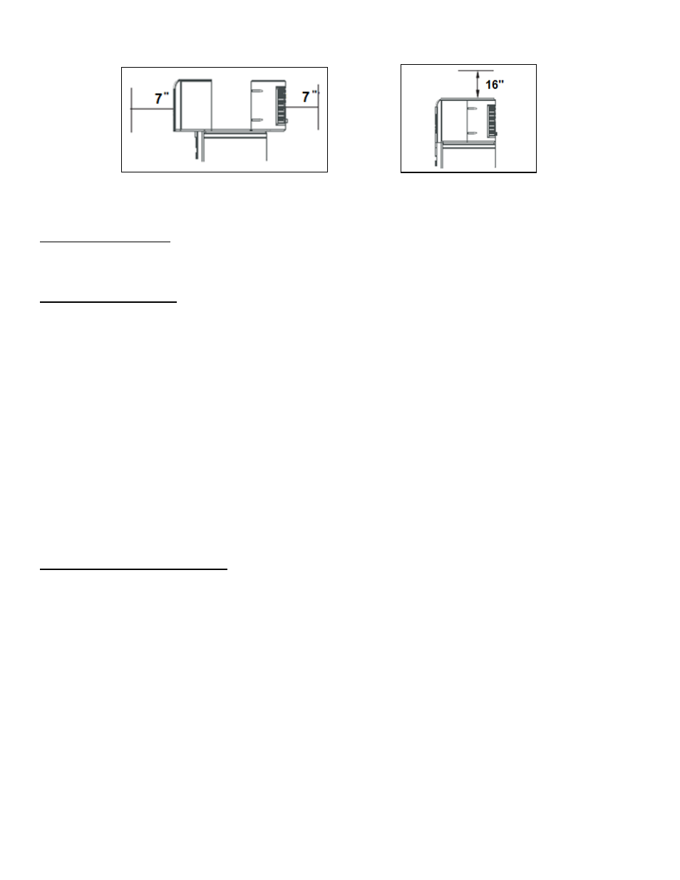
Figure 4
– Front and Rear Clearances
Figure 5
– Top Clearance
A 16
” minimum clearance is required to remove the filter for cleaning. The hot and cold water plumbing and electrical connections must
not interfere with the removal of the filter.
C. CONDENSATE DRAIN
The water heater has a condensate drain: therefore a drain must be available in close proximity to the unit. The drain must be no higher
than 36” above the floor (laundry drain is acceptable). If no drain is available, a common condensate pump with a capacity no less than
1 gallon/day must be purchased from a local plumbing supply store and installed.
D. THERMAL EXPANSION
Determine if a check valve exists in the inlet water line. It may have been installed in the cold water line as a separate backflow
preventer, or may be part of a pressure-reducing valve, water meter, or water softener. A check valve located in the cold water inlet line
can cause what is referr
ed to as a “closed water system”. A cold water inlet line with no check valve or backflow prevention device is
referred to as an “open water system”.
As water is heated, it expands in volume and creates an increase in the pressure within the water system. This action is referred to as
“thermal expansion”. In an open water system, expanding water which exceeds the capacity of the water heater flows back into the city
main, where pressure is easily dissipated.
A closed water system prevents the expanding water from flowing back into the main supply line, and the resulting thermal expansion
can create a rapid and dangerous pressure increase in the water heater and system piping. This pressure increase can quickly reach
the safety limit of the relief valve, causing it to operate during each heating cycle. Thermal expansion, and the resulting rapid and
repeated expansion and contraction of components in the water heater and piping system, can cause premature failure of the relief
valve and possibly the water heater itself. Replacing the relief valve will not correct this problem.
The suggested method of controlling thermal expansion is to install an expansion tank in the cold water line between the water heater
and the check valve (refer to the illustration in Figure 6). The expansion tank is designed with an air cushion built in that compresses as
the system pressure increases, thereby relieving the thermal expansion and eliminating the repeated operation of the relief valve.
Other methods of controlling thermal expansion are available. Contact your installing contractor, water supplier, or plumbing inspector
for additional information regarding this subject.
E. WATER SUPPLY CONNECTIONS
Refer to Figures 6, 7, and 8 for suggested typical installations. The installation of unions or flexible copper connectors is recommended
on the hot and cold water connections so that the water heater may be easily disconnected for servicing if necessary. The HOT and
COLD water connections are clearly marked and are ¾” NPT on all models.
NOTE: Install a shut-off valve in the cold water line near the water heater. This will enable easier service and maintenance of the water
heater.
IMPORTANT: Do not apply heat to the HOT or COLD water connections. If sweat connections are used, sweat tubing to
adapter before fitting the adapter to the cold water connections on the water heater. Any heat applied to the hot or cold water
connections will permanently damage the dip tubes.