Harrington Hoists and Cranes Static/Dynamic Hoist Load Tester User Manual
Page 7
7
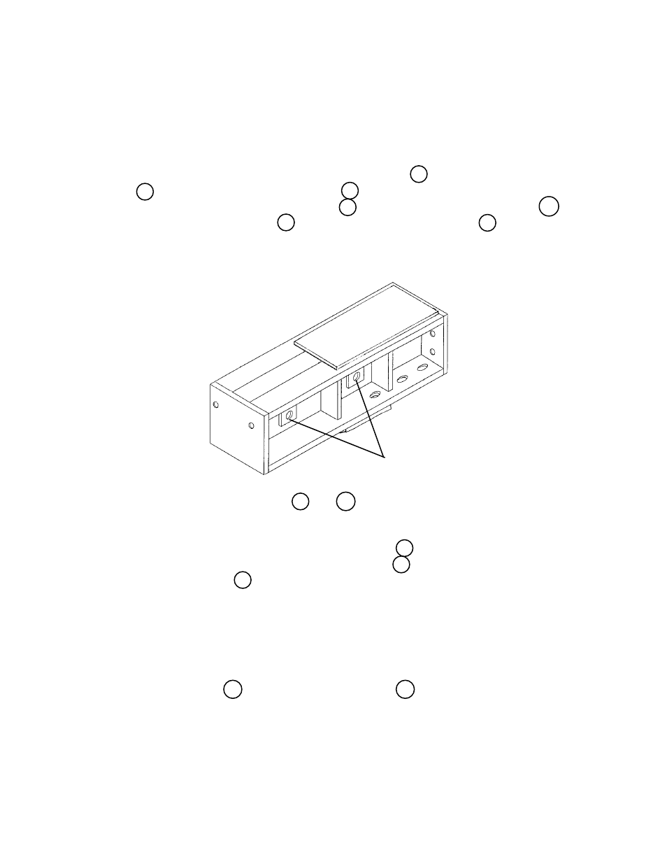
Step 5: Assembly of master links, item 9 and 10 , to the upper beam as shown on drawing
50979.
a.) Select the two (2) remaining short pins, item 7 , and the one (1) remaining
orange colored size 1 1/4" master link, item 10 , and the yellow colored size 1"
master link, item 9 .
b.) Insert the two (2) short pins into the pin holes and slide them partially through
the top beam.
c.) Place one (1) orange size 1 1/4" master link on the pin closest to the vertical
column and labeled 10 ton and place the yellow size 1" master link farthest away
from the vertical column and labeled 5 ton. Now slide the pins the remainder of
the way through the top beam and secure them by placing one (1) M8x60mm
long bolt, item 32 , and an M8 lock nut, item 33 , at each end of both pins as
shown in section A-A drawing 50979.
Step 4: Assembly of top beam, Figure #6, to vertical column, Figure #3.
a.) Remove the upper beam, Figure #6, from the shipping crate using a forklift or
bridgecrane.
b.) Lift the upper beam, Figure #6, to the top of the vertical column and couple them
by inserting six (6) M20x75mm long bolts, item 13 , six (6) M20 lock washer, item
14 , and six (6) M20x2.5 nuts, item 15 , as shown on drawing 50979. Also insert
six (6) M16x65mm long bolts, item 16 , six (6) M16 "U" washers, item 34 , six (6)
M16 lock washers, item 18 , and six (6) M16x2.0 nuts, item 19 , shown on draw
ing 50979.
c.) Make certain that all fasteners are tight by applying 187 foot-lb to the M16 fas-
teners and 367 foot-lb to the M20 fasteners, using a torque wrench.
Pin Holes
Figure 6