Harrington Hoists and Cranes CX Hand Chain Hoist User Manual
Page 5
Page 5 of 6
Table 5-4 Hoist Inspection Methods and Criteria – Continued
Item
Method
Criteria
Action
Load Sheave
Visual
Pockets of Load Sheave should be clean and free of significant wear.
Replace.
Warning Labels
Visual
Warning Labels should be affixed to the hoist and they should be legible. (see
Section 8.0, Figure Number 33
)
Replace.
Hoist Capacity
Label
Visual
The label that indicates the capacity of the hoist should be legible and securely
attached to the hoist.
Replace.
Table 5-5 Top Hook & Bottom Hook Dimensions
"u" Dimension
inch (mm)
"t" Dimension
inch (mm)
Product
Code
Nominal "k"
Dimension*
inch (mm)
Standard Discard Standard Discard
“k” Measured When New:
Top: ___________________
Bottom: _________________
CX003
1.35 (34.4)
0.49 (12.5)
0.47 (11.9)
0.43 (11.0)
0.41 (10.5)
* These values are nominal since the dimension is not controlled to a tolerance. The "k" dimension should be measured when the hook is
new - this becomes a reference measurement. Subsequent measurements are compared to this reference to make determinations about
hook deformation/stretch. See
Section 5-5
, “Hooks - Stretch”.
Table 5-6 Chain Wear Dimensions
"P" inch (mm)
"d" inch (mm)
Product
Code
Standard Discard Standard Discard
CX003
1.79 (45.5)
1.84 (46.8)
0.126 (3.2)
0.11 (2.9)
Table 5-7 Friction Plate Dimension "t"
Product
Code
Standard
inch (mm)
Discard
inch (mm)
CX003 0.20
(5.0)
0.18
(4.5)
Table 5-8 Top Pin Hole Dimensions "D"
Table 5-9 Top Pin Dimension "E"
Product
Code
Standard
inch (mm)
Discard
inch (mm)
Product
Code
Standard
inch (mm)
Discard
inch (mm)
CX003 0.33
(8.3)
0.35
(8.8)
CX003
0.33 (8.3)
0.35 (8.8)
6.0 Maintenance
6.1 For hoist maintenance or storage, comply with the following points.
6.1.1
DANGER
Do not lubricate the friction plate of the mechanical brake.
6.1.2
CAUTION
Always ensure that lubricant is applied to the load chain,
the top pin, the hook necks, the hook latches and the
select lever. Refer to
Section 2.1.4
“Hoist Parts”.
Do not store the hoist under a load.
Remove any dirt or water on the hoist.
Store the hoist in a dry and clean area.
Possibility of corrosion on components of the hoist
increases for installations where salt air and high
humidity are present. Make frequent and regular
inspections of the hoist’s condition and operation.
Perform all inspections given in “
5.0 Inspection
” if
irregularity of the hoist is found after operation
6.2 Disassembly/Assembly
6.2.1 When re-assembling the hoist, refer to parts list figure in
Section 8.0
for the proper component placement and orientation.
6.2.2
CAUTION
Load Limiter – Do NOT attempt to disassemble or adjust the
Load Limiter built into the Hand Wheel Assembly. Replace the Hand wheel
as an assembly with a new, factory adjusted part
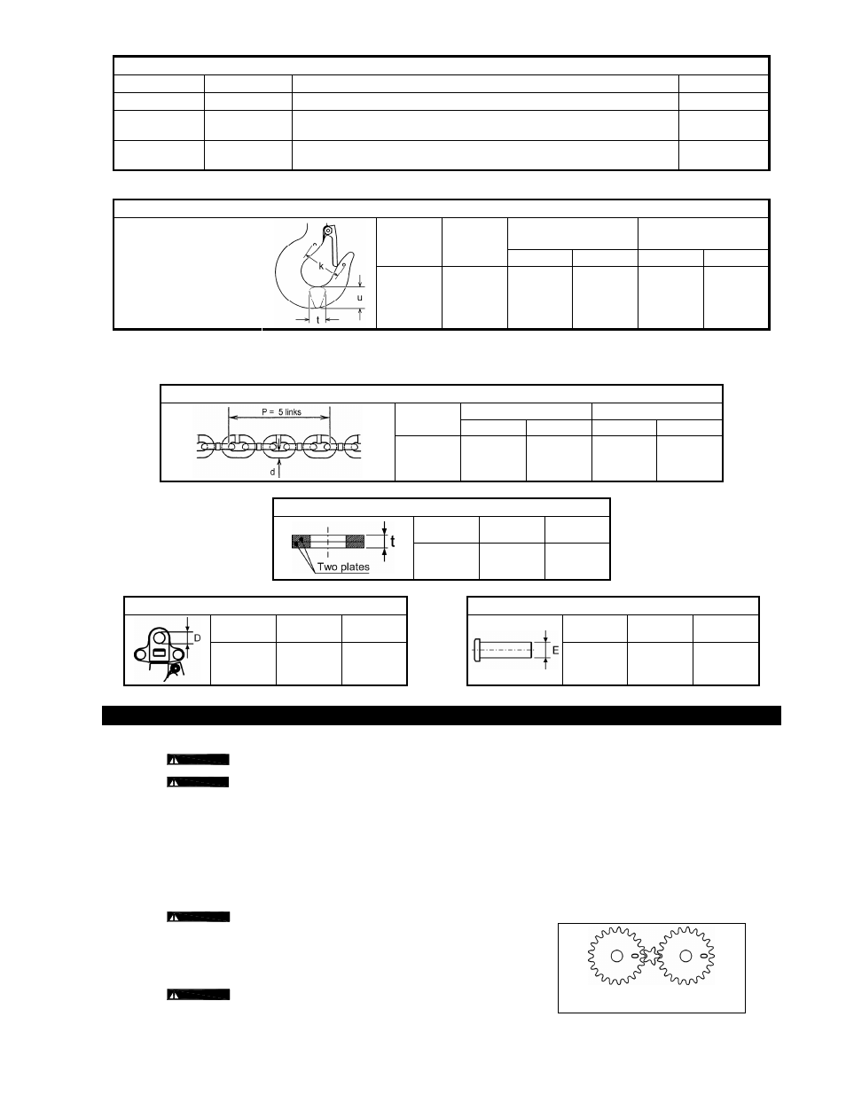
6.2.3 Gear timing – Installing the Gear #2's with the timing marks "O" oriented as
shown in
Figure 6-1
.
6.2.4
WARNING
Make certain the no-load end Load Chain is not twisted
when attached to the hoist body. See Section 2-1-4 for attachment point.
Figure 6-1 Gear Timing