Rivers Edge RE619 LumberJack Extrme User Manual
Page 23
Check for parts online at
www.huntriversedge.com or call 800-450-EDGE (3343) M-F 8-5
23
Operator's Manual
Rivers Edge One-Man Ladder Stands
1/4-20 x 2-1/2" bolts
platform spanner tubes
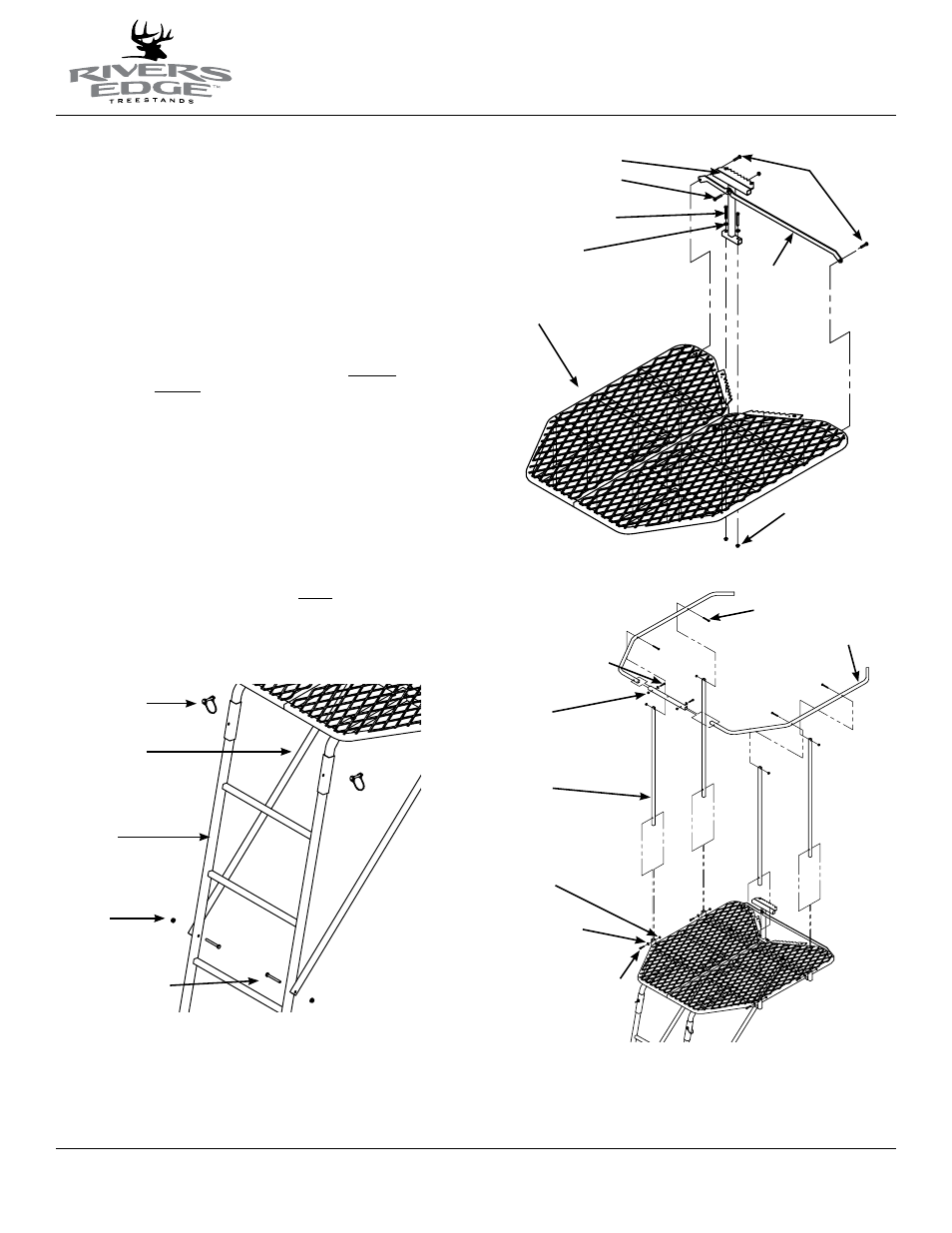
5. Insert the two ladder receiver J-pipes (already assembled onto the platform)
into the pockets of the top ladder section with side holes (SL78). Attach the
(2) support tubes (112ML75) to the outside of top ladder section using (2)
provided 1/4-20 x 2-1/4” bolts and locknuts. Secure the top ladder section
and assembled top platform section together using (2) provided spring lock
pins. Handle of spring lock pin must be put to the outside of ladder side
rails. SEE fIGuRE 3.
6. Attach the tree blade weldment (112ML73) to the top side of assembled
platforms (near welded on platform tree blades) using (2) provided 1/4-20
x 2-1/4” bolts, locknuts and steel washers. SEE fIGuRE 4.
notE: teeth of tree blade weldment should point to the rear of assembled
platforms, in the same direction as platform tree blades.
7. Attach (2) tree blade support braces (112ML76) to the front side of tree blade
weldment and back side of the assembled platforms using (3) 1/4-20 x 1-1/2”
bolts and (3) locknuts. SEE fIGuRE 4. Pay special attention to the orientation
of the support braces shown in figure 4.
8. Using the end with the greater distance from hole to end of tube, insert (4)
shooting rail uprights (112ML72) into pockets of platform spanner tubes.
Secure each upright in the pocket using (4) 1/4-20 x 1-1/4” bolts, locknuts
and steel washers. SEE fIGuRE 5.
9. Insert (2) curtain/shooting rail rims (112ML71) into each end of the rail
spanner tube (TWR26) and secure using (2) provided 1/4-20 x 1-1/4” bolts,
locknuts and steel washers. SEE fIGuRE 5. Pay special attention to the
orientation of shooting rail rims in figure 5.
10. Attach the assembled shooting rail to the inside of shooting rail uprights
using (4) provided 1/4-20 x 1-3/4” bolts & locknuts. SEE fIGuRE 5. You must
now tighten all nut & bolt assemblies. Be sure not to over tighten or
crush tubing when tightening!
Figure 3
spring lock pins
support tubes
top ladder section with
side holes
locknuts
1/4-20 x 2-1/4" bolts
Figure 4
1/4-20 x 1-1/2"
bolts
tree blade
support brackets
tree blade weldment
1/4-20 x 2-1/4" bolts
steel washers
1/4-20 x 1-1/2" bolt
assembled platforms
locknuts
Figure 5
1/4-20 x 1-3/4" bolts
1/4-20 x 1-1/4" bolts
locknuts
locknuts
steel washers
1/4-20 x 1-1/4" bolts
shooting rail uprights
shooting rail rim