Reversomatic Deluxe Series User Manual
Page 9
Programming Instructions for Wall Control Unit (cont’d)
7
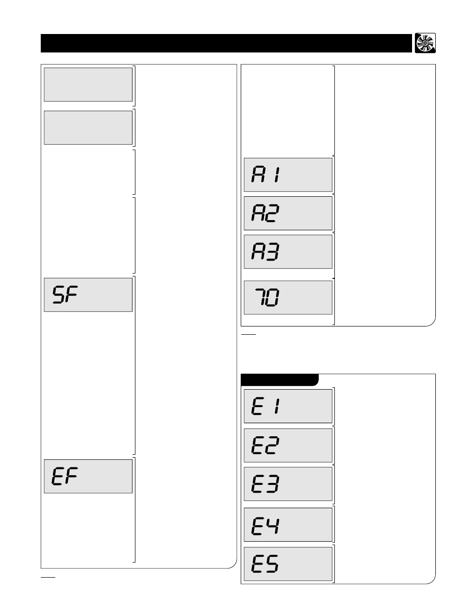
After pressing the MODE button,
the unit switches to Airflow
Balancing disable/enable setting.
The current value is enabled.
(Automatic Balancing mode)
PROGRAM
Press + button. The value is
changed to disabled.
(Manual
Balancing mode - for units
without built in automatic
Electronic Air Balancing)
NO BAL
PROGRAM
Press + button again. The value
is changed to enabled. When
you select the desired setting,
press MODE button. The setting
is reprogrammed with the new
value.
After pressing the MODE button,
the unit switches to wall control
address setting. The current
value is A1. (Wall control #1)
PROGRAM
PROGRAM
Press + button, The value is
changed to A2. (Wall control #2)
PROGRAM
Press + button, The value is
changed to A3 (Wall control #3).
When you select the desired
address, press MODE button.
The address is reprogrammed
with the new value.
%
OFF
After pressing the MODE button,the
unit return back to normal operational
made. The new programmed settings
are stored in the memory, & the
HRV/ERV will operate according to
them.
Displaying Errors
Loss of communication with the
Control Board. HRV/ERV
switched to OFF mode
automatically.
OFF
Defrosting Temperature Sensor
Failure. Blinks with the current
operational display. HRV
does not perform defrost cycles.
/ERV
NORMAL
NORMAL
Airflow Sensor Failure. Blinks
with the current operational
display. HRV
runs at fixed
default Low and High fans
speeds.
/ERV
Humidity Sensor Failure. Blinks
with the current operational
display. HRV/ERV does not run
in High Humidity mode.
NORMAL
If Airflow Balancing is enabled,
after pressing the MODE button,
the unit jumps to Wall Mount
address setting.
Else if Airflow Balancing is
disabled, after pressing the
MODE button, the unit switches
to
supply fan manual Airflow
adjustment mode.
“SF” is displayed when the unit
is in supply fan manual
adjustment mode.
Press + or - button to increase
or decrease supply fan speed.
“SF” blinks when the button is
depressed. It may take several
minutes to speed up or
slow
down.
Release of + or - button stops
supply fan speed change.
The changed supply fan speed
is stored in non-volatile memory
which will be used from now on
for the current airflow settings
(N1-N4 and H1-H4) can be
manually changed and stored in
non-volatile memory.
Note: Enabling of balancing
mode will cause manual fan
speed change back to default
settings.
Airflow
PROGRAM
After pressing the MODE button,
the unit switches to
exhaust fan
manual adjustment mode. “EF”
is displayed when the unit is in
exhaust fan manual airflow
adjustment mode.
Press + or - button to increase
or decrease exhaust fan speed.
“EF” blinks when the button is
depressed. It may take several
minutes to speed up or
slow
down.
Releasing of + or - button stops
exhaust fan speed change.
PROGRAM
The changed exhaust fan speed
is stored in non-volatile memory
which will be used from now on
for the current airflow settings
(N1-N4 and H1-H4) can be
manually changed and stored in
non-volatile memory.
Note: Enabling of balancing
mode will cause manual fan
speed change back to default
settings.
NORMAL
Fans Failure. Blinks with the
current operational display. HRV
stops fans, closes damper
& opens furnace / fan-coil /
heat pump interlock relay.
/
ERV
(Auto balancing unit only)
Note: Default Wall Unit Address is A1. If multiple Wall units are
installed, they must have different addresses (i.e. A2,A3) in
order to make communication work.
If the Wall Unit is in Programming mode and there is no
button pressing for timeout period of 60 sec., the Unit
returns automatically back in normal operational mode.
•
•
Note:
In manual balancing mode, we recommend SF & EF values
are adjusted by professional balancer or qualified contractor.
Note:- E3 & E5 will not be displayed on non-balancing unit.
see page-14 for possible causes and solutions.
(Auto balancing unit only)