Ransburg Serial Atomizer Module A11925-00 User Manual
Page 23
LN-9256-07.4
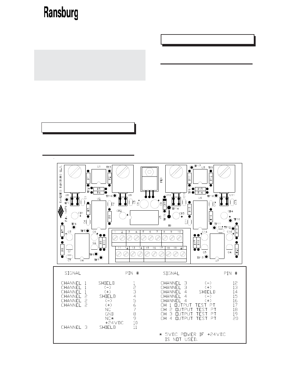
Serial Atomizer Module - Parts Identification
2 0
2 0
2 0
2 0
2 0
Figure 10: Transceiver Board
Figure 10: Transceiver Board
Figure 10: Transceiver Board
Figure 10: Transceiver Board
Figure 10: Transceiver Board
Operating Temperature:
Operating Temperature:
Operating Temperature:
Operating Temperature:
Operating Temperature: 0
°°°°° TO 70°°°°° C
Power Required:
Power Required:
Power Required:
Power Required:
Power Required: 24 VDC at 0.15 A or
5 VDC at 0.35A
Connections: Input power - Required input power
is +24 VDC or 5 VDC. Connect 24 VDC to
terminal “10” and 24 VRET to terminal “8”. For 5
VDC connect 5 VDC to terminal “9” and 5 VRET
to terminal “8”.
For the number 1 atomizer: connect a twisted pair
wire with shield to terminal 3 and 2 for “+” and “-”
respectively and to terminal 1 for shield. This wire
is connected at the other end to the first Atomizer
Module on TB2 V1 and V2 motherboard. Connect
the fiber optic cable from the first bell to the fiber
optic input labeled TP1 on the transceiver board.
Follow the same procedure for multiple atomizers.
The transceiver board is capable of receiving
signals from four bells (-02 = 2 bells, -04 = 4 bells).
The transceiver board mounts on a DIN rail.
T
T
T
T
Transceiver Board
ransceiver Board
ransceiver Board
ransceiver Board
ransceiver Board
Specifications
Specifications
Specifications
Specifications
Specifications
> If 24 VDC is used, do not connect
5 VDC terminal.
N O T E
N O T E
N O T E
N O T E
N O T E
> Connect terminal #8 to earth
ground and to pneumatic mother-
board TB1 terminal 2.
N O T E
N O T E
N O T E
N O T E
N O T E