Operation, Sw4 switch configuration – Ransburg Serial Analog Module A11012 User Manual
Page 14
LN-9258-07.2
Serial Analog Module - Operation
11
OPERATION
The Serial Analog Module provides a pneumatic
pressure signal output which is proportional to the
voltage input. Each module contains two channels
of control. The voltage input can be provided by
various methods; by a front panel control, by an
external 1-10 VDC signal, an external 0-10 VDC,
or external 4-20 mA signal. The front panel control
has a detent at full CCW. In this detent position,
the output responds to the external voltage input.
When this control is rotated CW from this detent,
the output responds to the position of the front panel
control. A "Local" signal is provided to indicate
that the output is controlled by the front panel. A
"Stable" front panel indicator and signal output
indicate that the output pressure has reached the
level set by the input signal.
>
Do not use lubricants that contain sili-
cone.
W A R N I N G
!
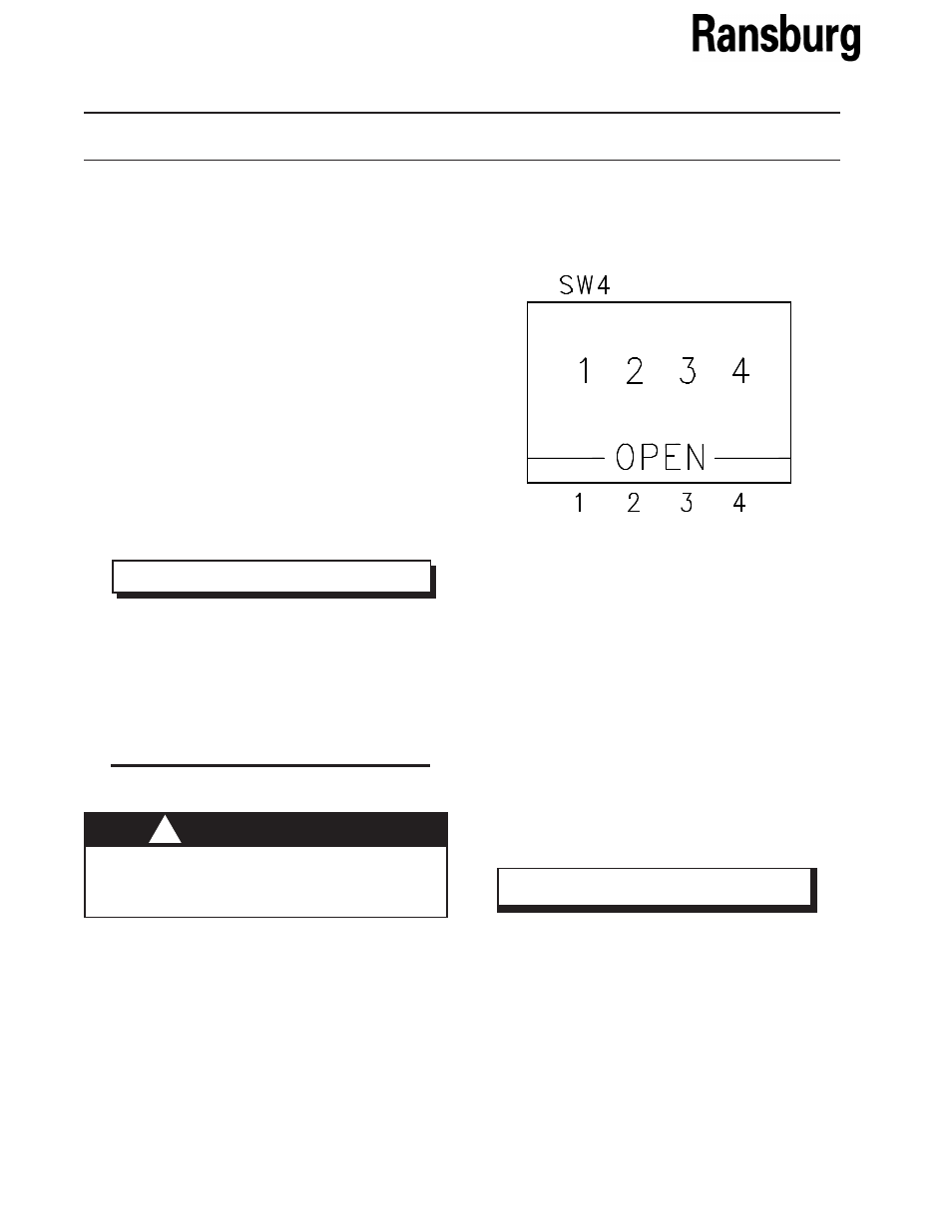
SW4 SWITCH
CONFIGURATION
1. "Open" position for pilot lines less than 50-ft.
of 5/32-inch tubing. "Closed" (opposite the
open position) for pilot lines more than 50-ft.
of 5/32-inch tubing.
2. Future Use
3. Future Use
4. "Open" position for 0-10 VDC remote input in
voltage mode.
"Closed" (opposite the open position) for 1-10
VDC remote input in voltage mode.
>
Before installing module, make sure the
o-rings (7554-03), located on the edge
connector of each pneumatic valve, are
in place and fully seated. Prior to install-
ing, put a small amount of lubricant on the
surface of each o-ring to prevent shearing
when installing.
NOTE
When one output is used to pilot a volume booster
(regulator), the volume booster must have a non-
bleed pilot, such as P/N: A11111.00. Use of a
volume booster with a bleed pilot will cause fluc-
tuating output pressure. When using the Serial
Analog Module for a retro-fit application, refer to
the last page of this Operation section for details.
NOTE