Lanair 215 Gallon Tank With Bypass Regulator User Manual
Page 9
Visit our website at: www.lanair.com
9
Section 3 - Plumbing Installation
PLUMBING INSTALLATION - By-Pass Regulator Assembly (cont.)
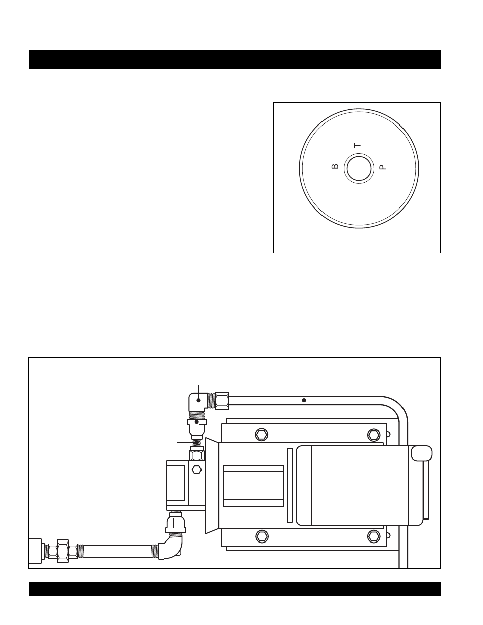
4. Install a 1/2" comp x 3/8" NPT brass elbow (P/N 8563) into
the port labeled "B" on the bottom of the by-pass regula-
tor (see Figs. 7 & 8). NOTE: The elbow should be facing up.
5. Install a 1/2" comp x 3/8" NPT brass elbow (P/N 8563) into
the port labeled "P" on the bottom of the by-pass regula-
tor (see Figs. 7 & 8). NOTE: The elbow should be facing
down.
6. Attach the by-pass regulator assembly (T) to the top of the
return line assembly (see Fig. 7) and tighten. NOTE: The
brass elbow (P/N 8114) facing up should face the front of
the tank and the return line MUST drop straight into the
tank. DO NOT MODIFY OR ADD ELBOWS.
7. Install a 1/8" close nipple (P/N 8882) into the pump head outlet as indicated in Fig. 9.
8. Attach a 1/8" x 3/8 " reducing coupling (P/N 8560) and 1/2" comp x 3/8" NPT brass elbow to the 1/8"
close nipple (see Fig. 9).
9. Install the 1/2" copper tube (P/N 8564) between the compression fitting of the pump assembly and
the compression fitting on the by-pass regulator (see Figs. 7 & 9).
FIGURE 8
Bottom of By-Pass Regulator
P/N 8560
Reducing Coupling 3/8" x 1/8"
P/N 8563
Brass Elbow
1/2" comp x 3/8" NPT
P/N 8564
Copper Tube 1/2" x 75"
To By-pass Regulator
P/N 8882
1/8" Close Nipple
PUMP ASSEMBLY
PUMP HEAD
FIGURE 9