Lanair 215 Gallon Tank With Bypass Regulator User Manual
Page 8
®
Section 3 - Plumbing Installation
QUESTIONS?... Contact Customer Service at 1-800-753-1601 M-F 8:00 am- 4:30 pm CST
8
PLUMBING INSTALLATION - Pick-Up Tube to Pump Plumbing (cont.)
5. Install a 1/4" close nipple (P/N 8647) to the pump head
(see Fig. 5, page 7).
6. Install a 1/4" x 1/2" reducing coupling (P/N 8558), 1/2" street
elbow (P/N 8902) and 1/2" x 5" nipple to the previously
installed 1/4" close nipple (see Fig. 5, page 7).
7. Separate the 1/2" union (P/N 8556) as indicated in Fig. 5.
8. Attach the separated part of the union to the 1/2" x 5" nipple.
Re-assemble the union and tighten.
9. Check to make sure all joints are tight. NOTE: Failure to do so will result in suction leaks (drawing air
into oil) causing the heater to operate improperly. Tighten the pump assembly to the bracket. Install
the vacuum gauge (P/N 8398 - included in the heater accessory kit) to the previously attached 1/2" x
1/4" x 1/2" tee (P/N 9412) as indicated in Fig. 6.
P/N 8398
Vacuum Gauge
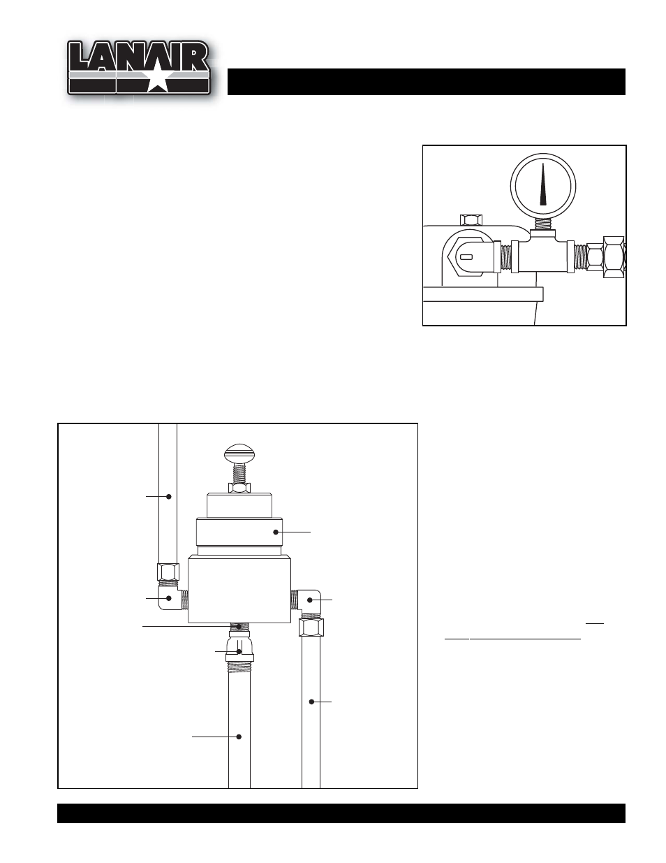
PLUMBING INSTALLATION -
By-Pass Regulator Assembly
Using a tube cutter, cut a 75" length
of tube from coil of 1/2" copper
1. Install the 1/2" x 48" by-pass
return line (P/N 9036) to the top
of the tank (See Fig. 3, page 6 for
hole location). NOTE: When
making plumbing connections,
use the thread seal compound
(P/N 5277) included in the
plumbing kit on all joints. DO
NOT USE TEFLON TAPE.
2. Attach the 1/2" x 3/8" reducing
coupling (P/N 9572) to the top of
the by-pass return line (P/N
9036) as indicated in Fig 7.
3. Attach a 3/8" close nipple (P/N
8475) to the previously installed
reducing coupling (P/N 9572) as
indicated in Fig. 7.
FIGURE 7
FIGURE 6
P/N 8563
Brass Elbow
1/2" comp x 3/8" NPT
To port "B"
P/N 8564
1/2""
Copper Tube
To Burner
P/N 8563
Brass Elbow
1/2" comp x 3/8" NPT
To port "P"
By-Pass Regulator
P/N 8564
1/2" x 75"
Copper Tube
To pump assembly
P/N 8475
3/8" Close Nipple
To port "T"
P/N 9572
Reducing Coupling
1/2" x 3/8"
P/N 9036
Return Line
1/2" x 48"
To top of tank