Lanair 215 Gallon Tank With Metering Pump User Manual
Page 9
®
Section 3 - Plumbing Installation
QUESTIONS?... Contact Customer Service at 1-800-753-1601 M-F 8:00 am- 4:30 pm CST
9
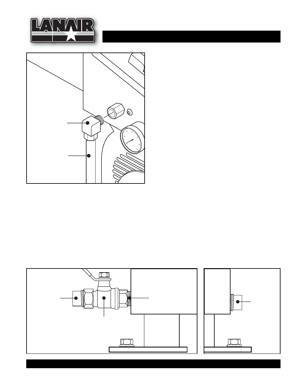
3/8" Copper Tube
To tee assembly
on pump
P/N 8917
Brass Elbow
3/8" comp x 1/4 NPT
FIGURE 8
PLUMBING INSTALLATION - To Burner
1. Attach the 3/8" comp x 1/4" NPT brass elbow (P/N
8917) as indicated in Fig 8.
2. Install the remaining 3/8" copper tube between
3. Assemble a 1/2” close nipple (P/N 8186, 1/2” x 1/4”
reducing coupling (P/N 8558), and 3/8” comp x
1/4” MPT brass elbow (P/N 8917). Install this assembly
into the 1/2” bung on the top of the tank. Connect a
3/8” copper tube from the relief valve on the metering
pump to the assembly described above (see Fig 3 & 8).
the compression fittings of the by-pass regulator
and burner (see Fig 8).
NOTE: Make sure all fittings are properly tight-
ened. Leaking fittings may cause delayed ignition
in the burner.
Tank Drain and Plug
1. Determine which side of the tank the drain will be on. On that side, install a 1/2" close nipple
(P/N 8186) to the drain hole (see Fig 9).
2. Install the 1/2" brass ball valve (P/N 8187) to the 1/2" close nipple. Install a 1/2" pipe plug (P/N 8185)
into the end of the ball valve (see Fig 9).
3. Install a 1/2" pipe plug (P/N 8185) into the hole on the opposite side of the tank (see Fig 10).
4. Vent the tank in accordance to state and local codes.
FIGURE 9
FIGURE 10
P/N 8186
1/2" Close Nipple
P/N 8187
1/2" Brass Ball
Valve
P/N 8185
1/2" Pipe Plug
P/N 8185
1/2" Pipe Plug