Lanair 215 Gallon Tank With Metering Pump User Manual
Page 8
®
Section 3 - Plumbing Installation
QUESTIONS?... Contact Customer Service at 1-800-753-1601 M-F 8:00 am- 4:30 pm CST
8
PLUMBING INSTALLATION - Pick-Up Tube to Pump Plumbing (cont.)
PLUMBING INSTALLATION - Pump to Burner Assembly
5. Install a 1/4" close nipple (P/N 8647) to the pump head
(see Fig. 5, page 7).
6. Install a 1/4" x 1/2" reducing coupling (P/N 8558), 1/2" street
elbow (P/N 8902) and 1/2" x 5" nipple to the previously
installed 1/4" close nipple (see Fig. 5, page 7).
7. Separate the 1/2" union (P/N 8556) as indicated in Fig. 5.
8. Attach the separated part of the union to the 1/2" x 5" nipple.
Re-assemble the union and tighten.
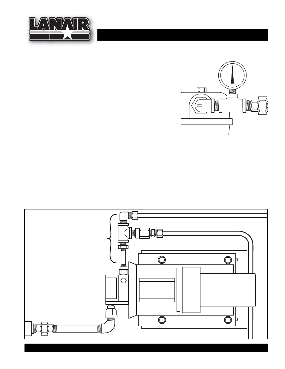
9. Check to make sure all joints are tight. NOTE: Failure to do so will result in suction leaks (drawing air
into oil) causing the heater to operate improperly. Tighten the pump assembly to the bracket. Install
the vacuum gauge (P/N 8398 - included in the heater accessory kit) to the previously attached 1/2" x
1/4" x 1/2" tee (P/N 9412) as indicated in Fig. 6.
P/N 8398
Vacuum Gauge
FIGURE 6
1. Install the Metering Pump Tee Assembly into the pump head outlet as indicated in Fig. 7.
2. Install the 3/8" copper tube (P/N 8921) between the compression fitting of the Metering Pump Tee
Assembly and and the compression fitting on the burner assembly (see Fig 7)
PUMP HEAD
FIGURE 7
METERING PUMP
TEE ASSEMBLY
(Included & Pre-Assembled
With Metering Pump)
(P/N 9981)
METERING PUMP
ASSEMBLY