General precaution – Argo and Kingsford's Cornstarch HLA User Manual
Page 2
THE EXTENSION KITS ARE SUPPLIED PRECHARGED
UNIT
NARROW TUBE
LARGE TUBE
MODEL
OUTSIDE DIA.
OUTSIDE DIA.
6,35 mm
7,93 mm
6,35 mm
9,52 mm
Separately insulated
●
Synthetic oil HAB - Alkylbenzene type ex. ZERICE S EXXON, about 30 gr.
●
PVC pipe to insulate hole in the wall, external diameter 50 mm. of minimum length as for thickness wall.
2
POWER SUPPLY 220 / 240V ~ 50 Hz
(TO BE CONTINUED AT PAGE 3)
Before the installation, verify that they are fit for the unit.
GENERAL PRECAUTION
●
Check that the voltage and frequency of the power supply
match those required by the system.
●
Check the possibility to have the power line to the indoor
unit (ELECTRIC CABLE LENGTH 3 m).
●
Install a double - pole switch, protected by 10 A fuses of the
delayed type, upstream the electricity wall socket.
●
Make sure that the electrical installation is suitable to supply
continuosly current necessary for the air conditioner in
addition to that already used by other electric appliances
(white goods, lighting). See the max electric imput indicated
on the name plate positioned on the air conditioner.
●
Before connecting the air conditioner to a power sock-
et, make sure that the socket is provided with an earth
connection in compliance with local codes.
●
Phillips head screw driver
●
Tape measure
●
Level
●
Hammer drill
●
Hole saw or key hole saw ø 50
●
19 mm
wrench
●
21 mm wrench
●
24 mm wrench
●
Hammer
●
Hacksaw
●
Core bits 10 mm diameter drill bit.
INSTALLATION SITE SELECTION
TOOLS REQUIRED FOR INSTALLATION (NOT SUPPLIED)
ADDITIONAL MATERIAL REQUIRED FOR INSTALLATION (NOT SUPPLIED)
INDOOR UNIT
AVOID:
●
Positioning the indoor unit into rooms where it could be
sprinkled with water (i.e. laundries).
●
To install in areas where
leakage of flammable gas or large amount of mist may be
expected humidity location.
●
Direct sunlight or near by heat
source that may affect performance of the unit.
●
Installing unit
behind curtains or furniture that obstruct air circulation.
DO:
●
Choose a position which allows proper ventilation in the
room.
●
Verify respect of the minimum recommended maintenance
space.
OUTDOOR UNIT
AVOID:
●
Direct sunlight or area where hot air from exhaust fans
investing the unit.
DO:
●
Choose a place as cool as possible and well ventilated.
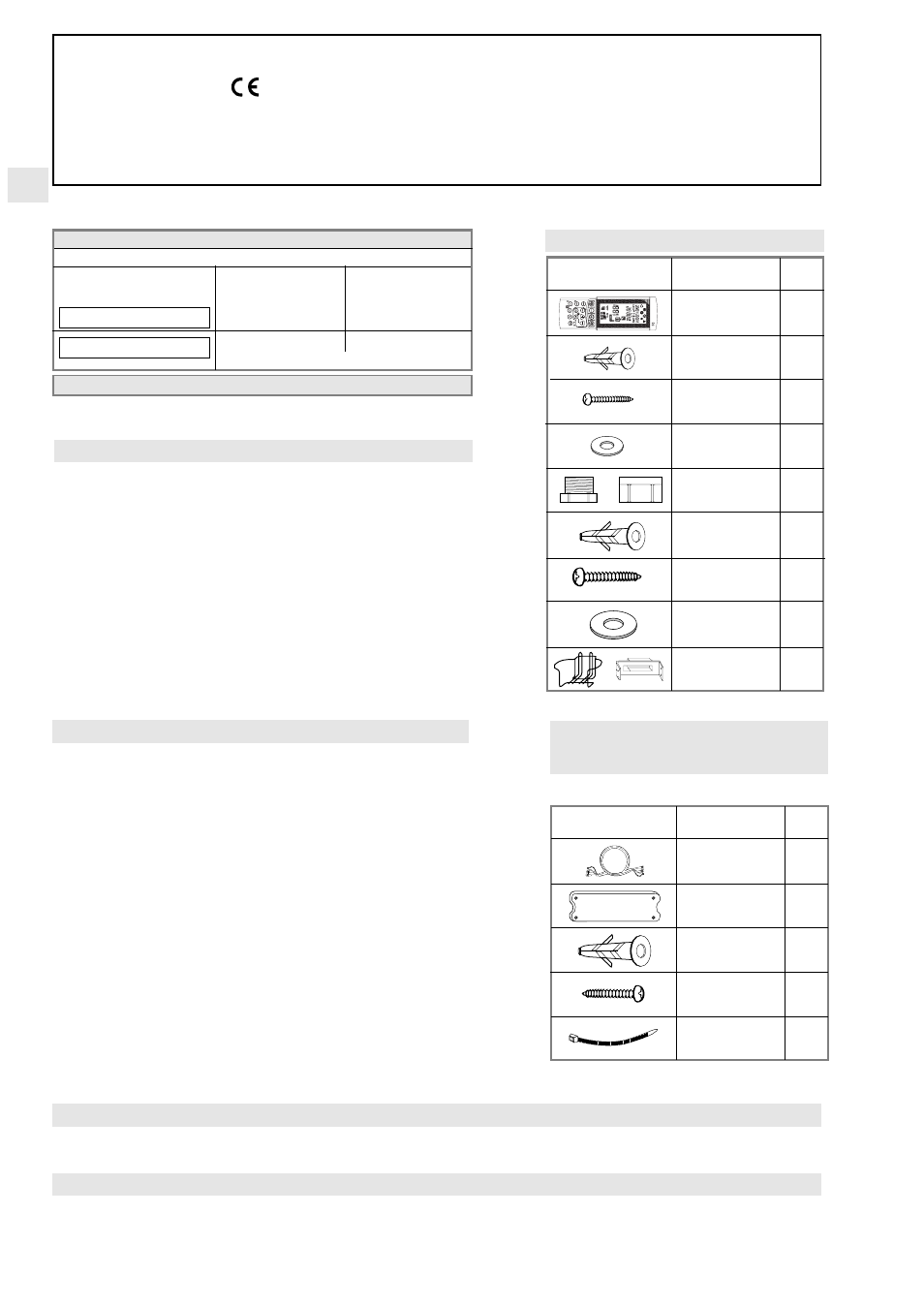
ACCESSORIES SUPPLIED WITH THE UNIT
PARTS
FIGURE NR°
REMOTE
UNIT CONTROL
1
RAWL PLUG S X 5
2
SCREW 4,2x32
2
WASHER
2
PLASTIC PLUG
(MALE AND
2 + 2
FEMALE)
RAWL PLUG
2/3
S X 10
SCREW 7x65
2/3
WASHER
2/3
OUTDOOR UNIT
BASKET OR
1
SUPPORT
CONNECTION EXTENSION KITS -
LENGHT OF 2 OR 4 m
ACCESSORY SUPPLIED ON REQUEST
* For heat pump version.
PARTI
FIGURA N°
EXTENSION KIT
FOR CONNEC-
1
TION TUBE
CONNECTIONS
1
PLASTIC BOX
RAWL PLUG
3
TAPPING SCREW
3
ø 3,5 x 45
CLAMP
2 + 8 *
EG
COOL/DRY/FAN
COOL/DRY/HEAT/FAN
DECLARATION OF CONFORMITY
This product is marked as it satisfies Directives:
– Low voltage no. 73/23 EEC and 93/68 EEC.
– Electromagnetic Compatibility no. 89/336 EEC, 92/31 EEC and 93/68 EEC.
This declaration will become void in case of misusage and/or from non observance though partial of Manufacturer's
installation and/or operating instructions.