Vh series, General pump – General Pump VH User Manual
Page 11
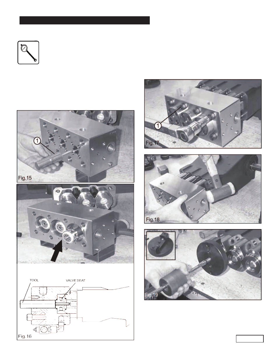
Remove the eight head screws (1, Fig. 17).
Once the head is removed the cylinders are free to be
taken out of the crankcase. Tapping the cylinders all
around with a plastic hammer helps loosen them from
possible scaling or deposit accumulated during use.
In order to facilitate the extraction of the cylinder the
tool p/n F200000180, or equivalent, is recommended
(Fig. 19).
Remove the pump head (see chapter 11.2).
GENERAL PUMP
A member of the Interpump Group
VH SERIES
Page 11
Reassemble valves and head back in place
by following the disassembling steps in the
opposite sequence and use a torque wrench
at the following settings for valve cover
screws and head screws:
-Valve cover screw: 54.2 ft. lbs.
-Head screws: 144.6 ft. lbs.
NOTE:
In order to facilitate reassembling operation use our tool
(1, Fig. 15) p/n F200000170, or equivalent, able to hold the
valve seat and valve poppet in place when mounting the
head on the pump (see arrow Fig. 16).
11.3 Pumping unit maintenance.
The only maintenance operation required for the pumping
unit is the visual check of the amount of water drained out
by the cooling system through the hole provided
underneath the head (Fig. 7, page 9). It clearly shows
the pressure packing state of wear. Pressure packings
should be replaced when vibration and/or drop in the
operating pressure start to occur during operation.