Vf series, General pump – General Pump VF Owner Manual User Manual
Page 9
GENERAL PUMP
A member of the Interpump Group
VF SERIES
Page 9
9.4 Hydraulic Connections
In order to isolate the system from the vibrations produced
by the pump, we advise to build the first section of the duct
near the pump (both for intake and delivery) with flexible
hose. The consistency of the intake section must allow to
avoid deformation caused by the depressurization
produced by the pump.
9.5 Pump Feeding
VF pumps require a minimum positive head (NPSH
r
)
ranging between 75 and 100 PSI (5 and 7 bar) measured
at head intake. The booster pump must have the following
characteristics: Flow rate of at least twice the value of the
plunger pump’s rated flow value, with a minimum pressure
of 75 PSI (5 bar). These feeding conditions must be
respected in all running conditions. Booster activation
must be independent from that of the plunger pump.
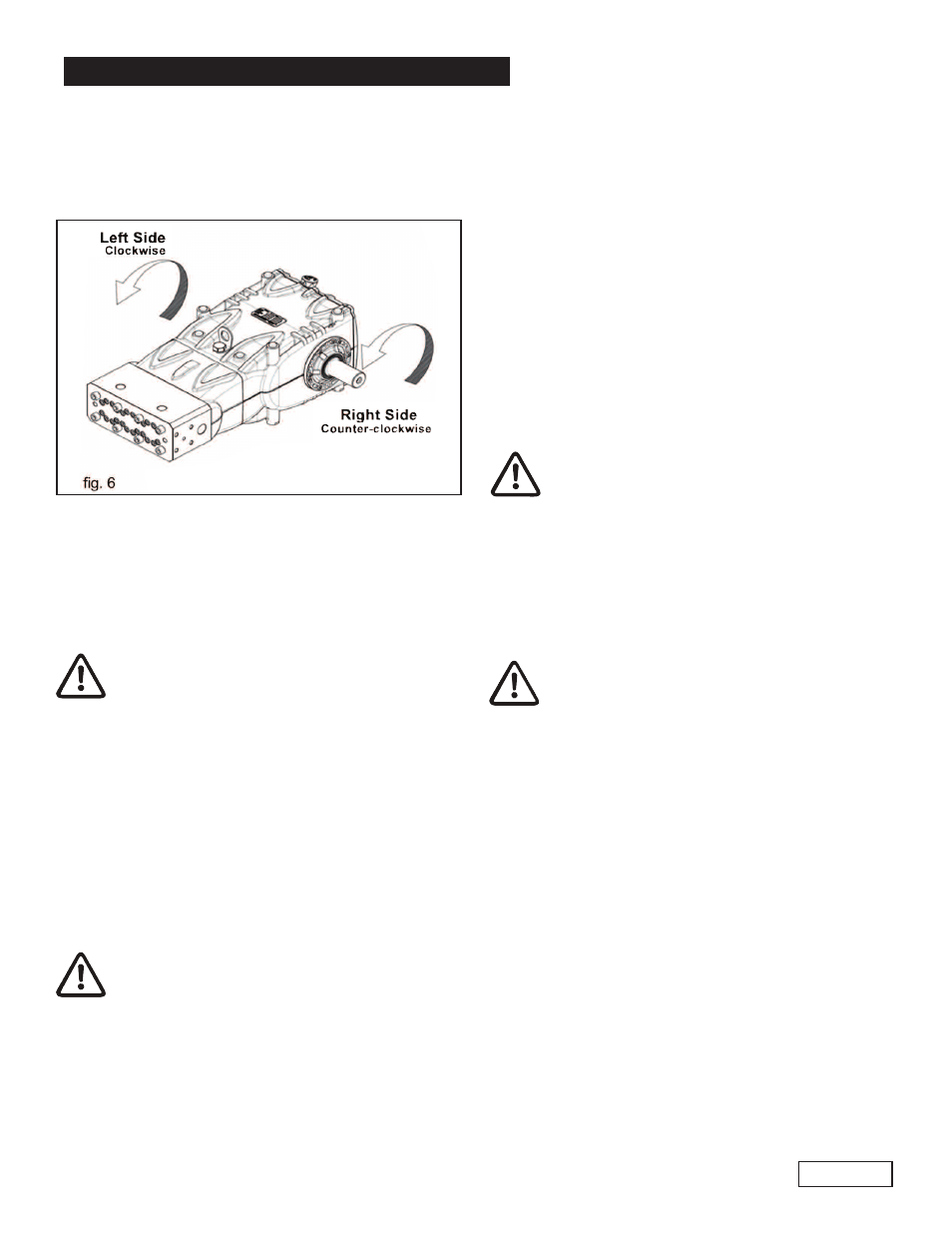
9.2 Direction of Rotation
An arrow situated on the crankcase near the shaft
indicates the correct direction of rotation. Standing in front
of the pump head, the direction of rotation must be as
shown in fig. 6.
9.6 Suction Line
For the pump’s correct operation, the suction line must
have the following characteristics:
1. Minimum internal diameter as indicated in the diagram
in paragraph 9.9, and in any case equal or greater than
the pump head’s value.
Along the duct, avoid localized diameter reductions
that may cause pressure drops with subsequent
cavitation. Absolutely avoid 90
0
elbows, connections with
other hoses, bottlenecks, counter-slopes, upside down “U”
shaped curves, “T” connections.
2. The selected lay-out must allow to avoid cavitation.
3. It should be perfectly airtight, and built in a way that
guarantees perfect sealing over time.
4. Avoid pump emptying when stopping (even partial
emptying).
5. Do not use hydraulic-type fittings,3 or 4 way fittings,
adapters, etc. , since they may hinder the pump’s
performance.
6. Do not install Venturi tubes or injectors for detergent
intake.
7. Avoid the use of standing valves, check valves, or any
other type of one-way valves.
8. Do not connect the by-pass line from the valve directly
to the pump suction line.
9. Provide appropriate baffle plates inside the tank in
order to avoid water that flows coming from both the by-
pass and feeding lines may create turbulence near the
tanks outlet port.
10. Make sure that the suction line is perfectly clean inside
before connecting it to the pump.
9.3 Version Change
A right version pump is defined when: observing the pump
from the head side, the PTO shank of the pump shaft is on
the right side.
A left version pump is defined when: observing the pump
from the head side, the PTO shank is on the left side.
The version may be changed only by
specialized and authorized personnel by care-
fully following the instructions that follow:
1. Separate the hydraulic part from the mechan-
ical part as indicated in Chapter 2, paragraph
2.2.1 of the repair manual.
2. Rotate the mechanical part by 180
0
, and repo-
sition the rear crankcase cover so that the oil
dipstick is facing upwards; reposition the lifting
bracket and the related closing caps in the
upper part of the crankcase; finally, correctly
reposition the identification plate in its
appropriate seat on the crankcase.
Be sure that the lower draining holes on
the crankcase near the plungers are open,
and not closed by the plastic caps that are
supplied.
3. Join the hydraulic part with the mechanical
part as indicated in Chapter 2, paragraph
2.2.2 of the repair manual.
Booster start-up must always precede plunger
pump start-up. In order to protect the pump,
we advise to install a pressure switch on the
feeding line after the filters.
Ref 300662 Rev.C
06-12