Vf series, General pump – General Pump VF Owner Manual User Manual
Page 10
GENERAL PUMP
A member of the Interpump Group
VF SERIES
Page 10
9.6 Suction Line (continued)
11. The pressure gauge for checking booster pressure
must be installed near the plunger pump’s outlet port, and
always after the filters.
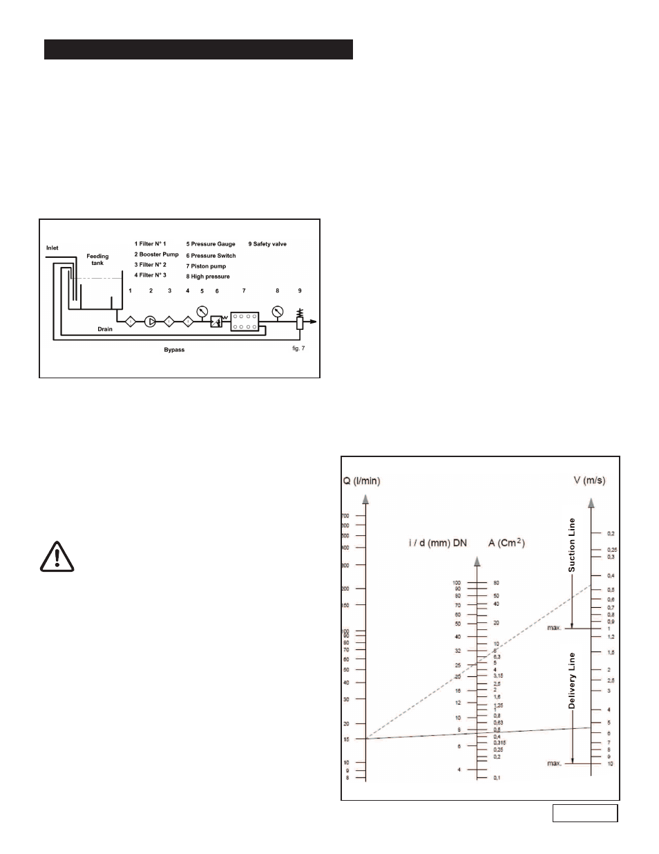
9.7 Filtering
The filtration degree for these pumps must be max. 20
micron; this is normally obtained by means of a series of
at least three filters, positioned as indicated in fig. 7.
The filter must be installed as close as possible to the
pump, should allow easy inspection and have the
following characteristics:
1. Minimum capacity 3 times greater than the pump’s
rated flow value.
2. Filter port diameters must not be smaller than the
pump inlet ports.
3. Filtration degree:
Filter No. 1: 250 micron
Filter No. 2: 100 micron
Filter No. 3: 20 micron.
In order to guarantee correct pump operation,
it is important to plan periodical cleaning of
the filter depending on actual pump usage,
water quality and real clogging conditions.
In order to guarantee the required feeding
pressure (see paragraph 9.5), install a
pressure switch.
9.8 Delivery Line
To obtain a correct delivery line, please comply with the
following installation instructions:
1. The internal diameter of the pump must allow to guar-
antee correct fluid speed; see diagram in paragraph
9.9
2. The first section of the hose connected to the pump
must be flexible in order to isolate pump vibrations
from the rest of the system.
3. Use high pressure hoses and fittings that guarantee
wide safety margins in any working condition.
9.8 Delivery Line (continued)
4. Install a safety valve on the delivery line.
5. Use pressure switches suitable for the pulsating loads
typical of plunger pumps.
6. In the design phase, take into proper account the
pressure drop along the line, since this causes a
reduction in usage pressure with respect to the value
measured at the pump.
7. If the pump pulsations are harmful for particular appli-
cations, install an appropriately sized pulsation damp-
ener on the delivery line.
9.9 Internal Diameter of the Hose Line
To determine the internal diameter of the hose, please
refer to the following diagram.
Suction Hose
With a flow rate of ~4 GPM (15 l/mn) and water speed of
0.5 m/sec. the diagram line that connects the two scales
intersects the central scale, indicating the diameters, at a
value of ~ 25 mm (1 inch).
Delivery Hose
With a flow rate of ~4 GPM (15 l/mn) and water speed of
5.5 m/sec. The diagram line that connects the two scales
intersects the central scale, indicating the diameters at a
value of ~ 8 mm (.31 inch).
Optimum speed values:
• Suction:
≤ 0.5 m/sec.
• Delivery:
≤ 5.5 m/sec.
Ref 300662 Rev.C
06-12