Instructions, Warning, Caution! tractor requirements and preparation – Farm Star LRHD-8 User Manual
Page 8: Connecting landscape rake to tractor, Packaging, Assembly and mounting, Assembly, Gauge wheel installation, Continued)
8
7
INSTRUCTIONS
WARNING!
Power unit must be equipped with R OPS or ROPS
cab and seat belt. Keep seat belt securel y fastened.
Falling off power unit can result in death fr om being
run over or crushed. Keep foldable ROPS systems in
“locked up” position at all times.
Be sure y our tractor and loader is in good condi-
tion. Read all the saf ety precautions and make sure
all equipment operator s are familiar with the saf ety
rules of operation.
CAUTION!
TRACTOR REQUIREMENTS
AND PREPARATION
——————————————————
The DCR, MCR, and LRHD Ser ies Landscape Rak es
will fit most Category I) tractors equipped with a standard
3 point hitch. DCR Ser ies rakes will also fit Categor y 0
hitch tractors.
NOTE: Some Categor y 0 tr actors ha ve v ery shor t lift
arms or
5
/
8
” diameter (Cat. 0) lift arm ball ends. The DCR
Series rakes will fit these tractors if equipped with special
Cat. 0 pullpins. The pins need to be installed to the inside
of the 3 pt. frame.
Check the tractor’s 3 point hydraulic lift system.It should
operate up and down smoothly and hold its position when
set. Refer to your tractor owner’s manual or dealer for any
adjustments necessar y to put the 3 point h ydraulic lift
system in good working order. (I&T shop manuals will list
most specifications and adjustment instr
uctions –
available from most farm equipment dealers.)
Tractor should be equipped with stabiliz er bars ,
adjustable sway chains, or sway blocks to keep the imple-
ment from swinging side to side.
Smaller size tractors may need front counter weights to
counter-balance the weight of the implement.
CONNECTING LANDSCAPE
RAKE TO TRACTOR
——————————————————
ALL MODELS
The landscape r ake is compatib le with Categor y 1, 3
point tr actors equipped with side s wing-type lo wer lift
arms and some Category 0 tractors.
1. To avoid interference with the landscape r ake, adjust
tractor drawbar to the shortest and highest position.
2. Attach the tr actor’s lo wer lift ar ms to the landscape
rake and secure in place with loc k pin.
For Category 0 Hitch application, order optional pull pin
kit part #590331 (one pair); replace the Categor y 1 pins
with the Category 0 pins. Make sure the Category 0 pins
are on the inside.
3. Tractor m ust be equipped with stabiliz
er bars ,
adjustable s way chains , or s way b locks to k eep the
implement from swinging side to side.
4. Attach the tractor’s top link to the top of the landscape
rake’s mast and secure with the top link pin and retain-
ing pin supplied with the top link.
IMPORTANT
■
■
Make sure rake is at least 6” (15 cm) fr om tractor
tires thr oughout complete rang e of 3 point hitc h
operation.
Level the A-fr ame and tinebar with 3 point connecting
links and top link. Adjusting the top link length will change
the fore and aft pitch of the teeth.
Lengthening the top link will cause the teeth to contact
the ground with a sharper pitch and be more aggressive.
You may need to adjust the optional gauge wheels after
adjusting pitch to maintain the desired w orking depth.
PACKAGING
——————————————————
The landscape rake is shipped as two bundles:
1. Main Frame with pull pins, bolts and nuts.
2. Rake Tine Bar Assembly (Teeth installed).
ASSEMBLY AND MOUNTING
——————————————————
Preview the assemb ly instr uctions and the e xploded
view of the landscape rake in your operator’s manual and
become f amiliar as to ho w the par ts or assemb lies go
together.
Select an area for assembly that is clean and free from
debris.
The two main subassemblies of the landscape rake are
heavy and a wkward to handle . It is recommended that
you have one or two helpers to complete the assembly.
1. On DCR and MCR models, assemble the “A” frame as
shown in the exploded parts view (pg. 12 or pg. 13).
2. It is suggested that y ou mount the main fr ame on the
3 point hitch of y our tr actor bef ore assemb ling the
landscape rake as follows:
a. Lower the 3 point hitch on y our tractor to facilitate
mounting of the main fr ame of the r ake to the
tractor.
b. Insert the lift ar m pins on the main fr ame into the
ball sockets in the lift ar ms of the tr actor 3 point
hitch. Pin in place with linchpins (not fur nished).
NOTE: On DCR models – if your tractor has a Category
0 3 point hitch (20” drawbar spacing), then the lift ar m
pins m ust be installed to the inside of the fr ame. If the
tractor has a Categor y I 3 point hitch (26”
drawbar
spacing), then the pull pins m
ust be installed on the
outside of the frame.
c. Attach the mast of the main frame to the tractor by
installing the tr actor center (or top) link with a top
link pin (not furnished).
NOTE: Use stabilizer bars, adjustable sway chains, or
sway b locks on y our tr actor lift ar ms to k eep the land-
scape r ake from s winging side to side . An anti-s way
device is a
must if oper ating the landscape r ake in a
reverse (pushing) position.
3. Install the r ake tine bar assemb ly to the mounting
frame and retain with 1” bolt, flat washer and locknut.
The locknut should be just loose enough f or the rake
assembly to pivot.
ASSEMBLY
(continued)
——————————————————
GAUGE WHEEL INSTALLATION
——————————————————
SINGLE WHEEL PACKAGE
(DCR Models Only)
Refer to the par ts illustration and assemble the wheel
package to the center of the r ake frame weldment using
(4) bolts, nuts and washers as shown. Grease the wheel
upon initial assembly.
DUAL WHEEL PACKAGE
(Recommended for rakes above 6’ in width
and all MCR and LRHD Series rakes)
Refer to the par ts illustr ation and install the gauge
wheel arms approximately one f oot in from each end of
the rake using longer carriage bolts provided. Grease the
wheels upon initial assembly.
Set up gauge wheels to the desired height using the
spacers and washers provided. Lock caster wheel spindle
in place with linch pin.
The operator is responsible for the safe operation of this
equipment. The oper ator m ust be proper ly tr ained.
Operators should be familiar with the tractor and attach-
ment, and all saf ety practices before star ting operation.
Read the safety rules and safety signs on pages 3-6.
INSTRUCTIONS
(continued)
FOR MODEL LRHD RAKES ONLY
For Category 1 Quick Hitch application, order optional
bushing kit par t #862500 (one pair); place bushing over
draw pin and fasten with roll pin.
For Quick Hitch application, the top center hitch hook
will seat into w elded 1
1
/
4
” diameter pin. This pin does not
interfere when unit is used with a standard 3 point hitch.
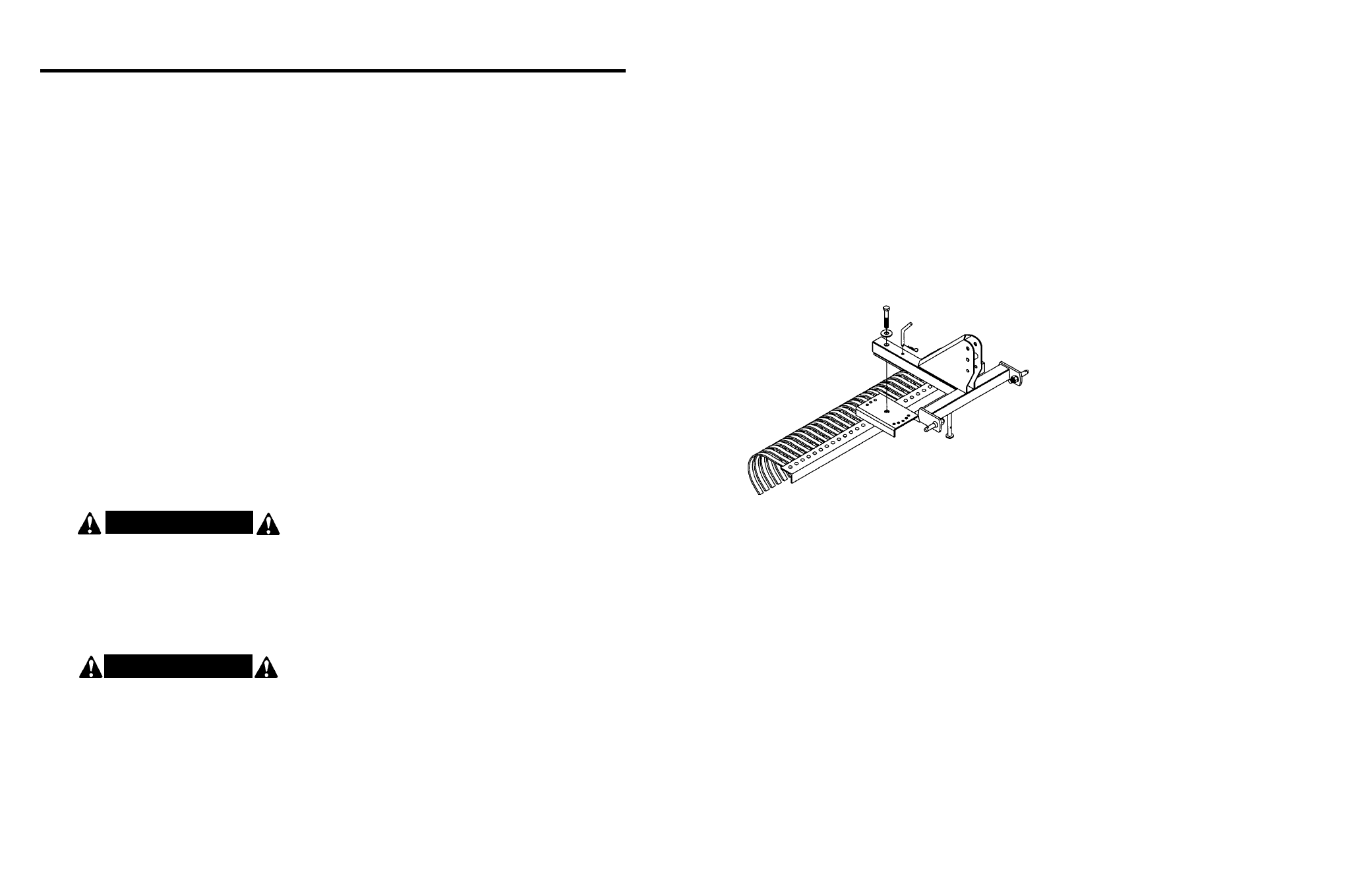
FOR MODEL LRHD RAKES
Place jack stands or suitab le blocking under tinebar so
center pivot bolt and 3 pt. mount can be installed.
Place 3 pt. frame assembly on top of the tinebar and
align 1 inch pivot hole with center hole on tine bar .
Install 1 inch pivot bolt and flat w asher. Tighten bolt so
3 pt. mount will swing but without excessive looseness.
Place 3 pt. frame in desired position and install angle
shift pin.
Place par king stand in position to suppor t landscape
rake.