Airvantage servicing - sensor assembly – Blagdon Pump AVX75 Metallic User Manual
Page 26
avx75mdl1sm_haz duty-rev0112
Model AVX75 Hazardous Duty Metallic Page 24
A
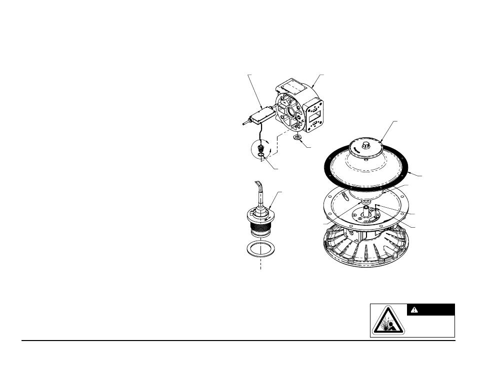
PLATE,
OUTER DIAPHRAGM
DIAPHRAGM
PLATE,
INNER DIAPHRAGM
BUMPER
PROBE TIP
O-RING
BRACKET, INTERMEDIATE, ASSEMBLY
SENSOR, FEEDBACK
NUT
SEAL
FLAT EDGE
DETAIL A
Note: Refer to Composite Parts
List on page 11 for part numbers
AirVantage Servicing -
Sensor Assembly
To service the control module, first shut off and bleed the air being supplied to the pump. For safety
purposes the air supply line should be disconnected from the pump. Then shut off the suction and
discharge lines to the pump. Bleed the pressure from the pump suction and discharge lines and remove
the lines from the pump. During the servicing of the AirVantage, consult the “AirVantage Composite
Repair Parts Drawing”.
Step #1: Remove the Patch Cable
• Twist the ribbed portion of the patch cable connector in a counterclockwise direction, until it
unthreads from the connector. The cable can either be removed from the intermediate or from the
control module.
Step #2: Remove the AirVantage from the Pump
• Use a ½” socket and remove the four 5/16-18 x 5 cap screws that hold the AirVantage to the
pump. Be sure to support the weight of the AirVantage while removing the last cap screw. After the
AirVantage is removed from the pump, set the unit down on the plastic cover located on the bottom.
Inspect the o-ring between the poppet valve and the adapter plate for damage.
Step #3: Diaphragm Disassembly
• Refer to the “Diaphragm Servicing” section (p.14) of the manual to remove diaphragm assembly
from the pump.
• “airVantage caution” – When the diaphragm assembly is removed, watch for the brass
probe tips located on the end of the sensor rod. there is one brass probe tip and one o-ring
per side. inspect the probe tips and o-rings for wear. for every diaphragm service, these
parts should be replaced and are available in kit form. consult the “composite repair Parts
Drawing” for part numbers and quantities.
Step #4: Accessing the Sensor Assembly
• Use a ¼” hex key wrench and remove the four, flat head socket cap screws on each inner chamber.
These bolts have been assembled using blue thread locker, so they may be difficult to remove. The
inner chambers and gaskets can now be removed.
• “airVantage caution” – remove the inner chamber from the intermediate with caution,
taking care not to damage the sensor.
• If the sensor needs to be replaced, use a 13/16” socket and remove the plastic nut holding the
connector to the intermediate. Slide the connector out of the hole.
• The sensor can now be removed from the intermediate assembly.
Step #5: Reinstallation
• Slide the new sensor assembly in the intermediate.
• “airVantage caution” – Make sure the cable assembly fits into the groove machined in the
intermediate. failure to do so may damage the cable during assembly.
• Feed the connector through the hole in the intermediate and install the plastic nut. Hand tighten the
nut using a 13/16" socket. Make sure the gasket is to the inside of the intermediate.
• The inner chambers and gaskets can now be reinstalled. Use blue thread locker on the inner
chamber bolts and torque them to 300 in-lbs.
• Refer to the “Diaphragm Servicing” section of the manual to finish the diaphragm installation
procedure.
Do not open when an
explosive atmosphere
may be present.
WARNING