Blagdon Pump X25 High Pressure User Manual
Page 13
HG-CF-1194-A - 12.02.10
Page 13
TECHNICAL NOTES :-
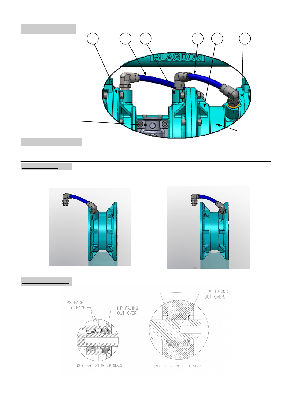
Air Hose connections :-
Air Hoses (items 32 & 36) are connected as shown, Inner Cover (Valve Chest) L.H. (47) connects to LH Spacer Cover (51) and Inner Cover
(Valve Chest) RH (37) connects to RH Spacer Cover (51) when looking from the Valve Block side of pump.
Spacer Covers
on right.
Valve Block on left.
47
37
32
36
51
LH
51
RH
25-085
25-110
25-111
Spacer Assembly :-
The Space and Cover assembly can be built in one of two ways as shown below. This does not effect the operation of the pump or the
connection of the hoses. On re-connection ensure hoses connect to the correct corresponding Valve Chest cover as shown below.
LH SPACER
COVER
RH SPACER
COVER
LH SPACER
COVER
RH SPACER
COVER
TO LH VALVE
CHEST COVER
TO RH VALVE
CHEST COVER
Lip Seal positions :-