System design, Service & repairs – Fire Fighting Enterprises Talentum UV/IR2 Flame Detector User Manual
Page 6
6
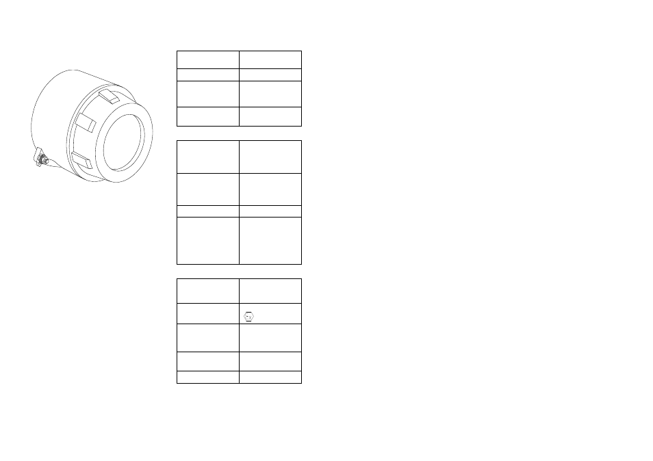
Flameproof Flame Detector
(Stainless Steel Housing)
Fig. 2
Technical Data
Mechanical
Housing Material:
See figure 2
316 Stainless Steel
Housing Colour:
Natural
Housing
Dimension:
(Excluding Mounts)
Height = 150mm
Width = 146mm
Depth = 137mm
Cable Gland
Entries:
3 X 20mm - typical
Electrical
Supply In:
Voltage
Current
Polarity sensitive
Terminals 1(+) & 2(-)
14 to 30Vdc
2 to 28mA
See data
sheet for detail
Optional Input:
Voltage
Current
Polarity sensitive
Terminals 3(+) & 4(-)
14 to 30Vdc
40µA
typ. @
24V IN
Power Up Time: 2 seconds
Relays
Contact Ratings:
Voltage
Current
Power
Resistive Loads Only
Terminals 5 to 8
30Vdc. Max.
1 Amp. Max.
30W Max.
Environmental
Operating Ambient
Temperature:
Check detector data
sheet.
ATEX
Approval Category
II 2 G D
CENELEC / IEC
Marking
EEx d IIC T6
Zone 1, 21, 2 & 22
Apparatus
Certificate Number
ISSeP 03ATEX012
IP Rating
IP66
7
System Design
Engineers familiar with codes of practice for
hazardous area systems should only
undertake the design of an flameproof fire
detection system. In Europe the standard is
EN 60079-0 (formally EN 50014), Electrical
apparatus for potentially explosive
atmospheres – General requirements.
The fire detector performance is the same as
the standard none flameproof counterparts.
Performance information given in standard
product guides is therefore applicable to the
flameproof range.
The ISSeP certification of the flameproof
device enclosure covers their characteristics
as components of a flameproof system. This
indicates that the flame detectors can be
used with a margin of safety in such
systems.
Service & Repairs
1.
Frequent inspection should be made. A schedule for the maintenance check should be
determined by the environment and frequency of use but should be regular enough to
ensure the detector continues to operate in the designed manner. It is recommended that
it should be at least once a year.
2.
External surfaces of the enclosure should be periodically cleaned to ensure dust deposits
are not allowed to accumulate.
3.
Check flamepath/threads on enclosure body and lid for signs of corrosion. If badly pitted,
replace component.
4. All components that are replaced must be in accordance with the manufactures
specification. Failure to use such components may invalidate the certication/approval on
the enclosure and may make the enclosure dangerous.
5.
After inspection and maintenance have been carried out, items 3 & 4 of the installation
instructions should be adhered to when resealing the enclosure.
Servicing of the fire protection system should be carried out as recommended by the local regulation
in force.