Fire Fighting Enterprises FIRERAY 2000 (Legacy) User Manual
Page 6
Fireray 2000 Installation Guide 22318.00.R 25.08.05
6
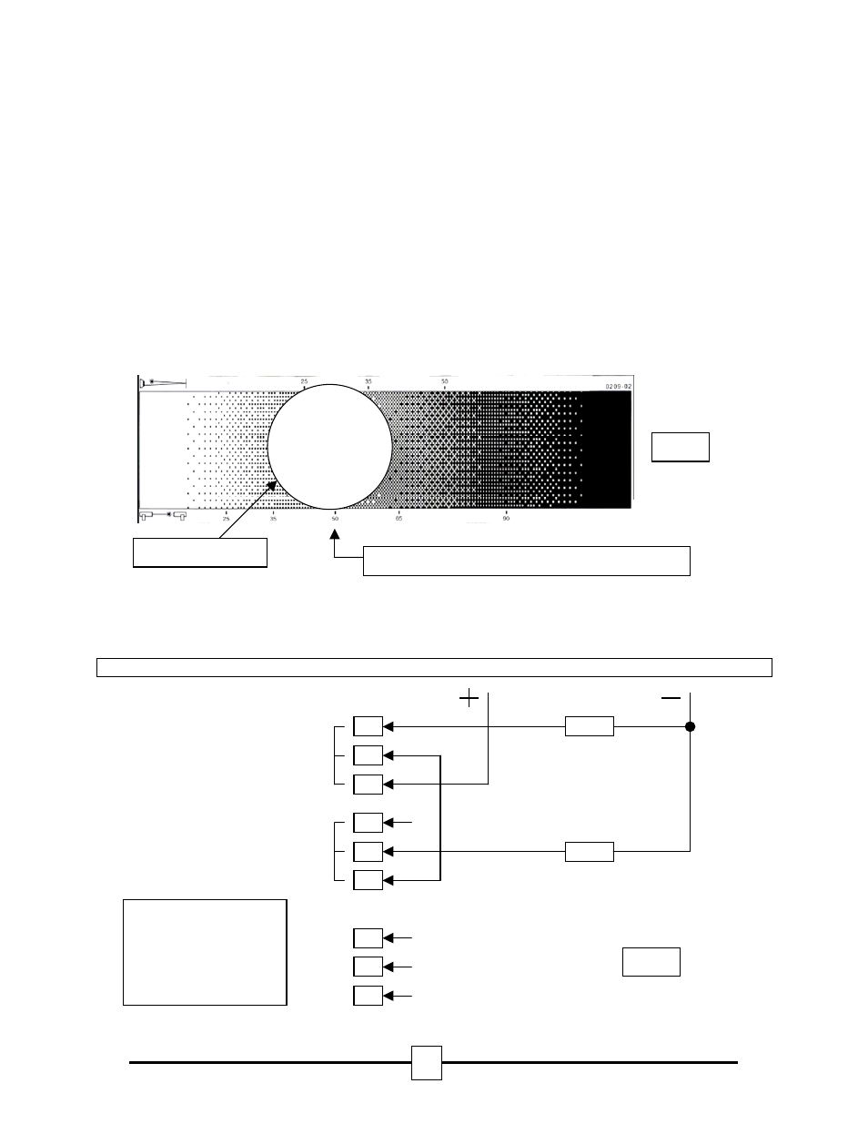
Alarm Test
1. Taking note of the threshold selected during installation (default 35%).
2. Select obscuration mark on filter to correspond with the Detector alarm threshold (see fig. 4).
3. Place the filter over the Receiver just past the correct obscuration value determined by the threshold
selected. For example if a threshold of 35% has been selected position the filter just past the 35%
obscuration value on the filter (see fig 4 below).
4. The Control Unit will indicate a fire within 10 seconds by activating the RED LED on the Control Unit door
and operating the fire relay.
Reset After Alarm Test
1. Remove the filter from the front of the Receiver, the Control Unit will reset after approximately 4 seconds if
the alarm latch option is configured as auto reset (default setting – switch open).
2. If the latching alarm option has been selected (switched closed) the Control Unit can be reset by either:
• Switching the TEST/RESET switch to ON, then OFF.
• Disconnect the power to the Control Unit for more than 1 second.
• By shorting the external reset terminal on the Control Unit PCB to the negative terminal for more than 1
second.
Fault Test
The fault relay and the fault LED operate if the beam is totally blocked for approximately 10 seconds.
Removing the obstruction will automatically reset the beam after approximately 4 seconds.
Typical Single Zone Wiring
Í Obscuration value
Receiver Optics
Align filter for correct obscuration/threshold setting
End of Line Component
Alarm Resistor
N/O
N/C
COM
N/O
N/C
COM
ALARM
FAULT
+
Earth
-
+VE (12-24 Vdc)
Earth
-VE (0V Return)
Fig 4
Fig 5
N.B. Alarm resistor and
End of Line Component
are not supplied.
Please contact Fire
Panel Manufacturer for
correct values.