Fire Fighting Enterprises FIRERAY 2000 (Legacy) User Manual
Page 5
Fireray 2000 Installation Guide 22318.00.R 25.08.05
5
Alignment Method ‘A’ Using Fireray 2000 Alignment Tool
1. Connect the Fireray 2000 alignment tool (optional extra – contact sales for details) to the Control Unit.
2. Position the Alignment Tool so that the LED’s are visible from the Transmitter
3. On the Control Unit PCB set the RESET/TEST switch to ON, and adjust the signal level potentiometer to 12
‘o’clock
4. Adjust the Transmitter orientation whilst observing the LED’s on the Alignment Tool.
5. If the green LED is steady and moving the Transmitter in any direction causes the green LED to flash, the
beam is aligned. Leave the Transmitter in the steady green LED position (go to 8).
6. If moving the Transmitter in any direction causes the red LED to flash, move the Transmitter in that
direction to obtain the red flashing LED (go to 7).
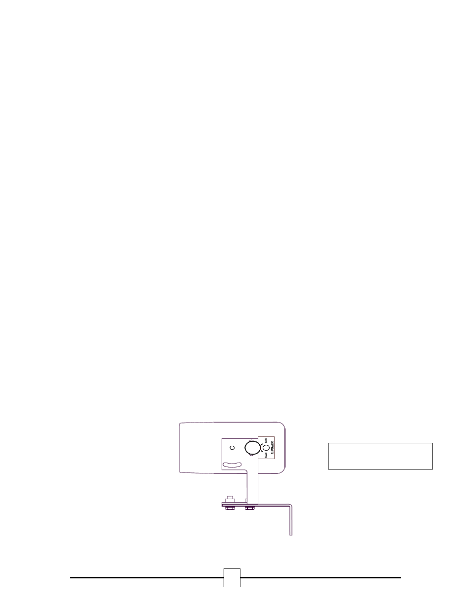
7. If the red LED flashes reduce the power of the Transmitter by removing the cap on the side of the
Transmitter (See fig 3) and using a small screwdriver turn the potentiometer clockwise until the red LED
stops flashing and the green LED stays steady (go to 5).
8. Secure the Transmitter by tightening both the screws in the bracket and recheck the Alignment Tool LED.
9. Continue to Final Settings After Alignment.
Alignment Method ‘B’ Using Voltmeter
1. Connect a voltmeter to the Test Meter terminal and ground on the Control Unit PCB.
2. On the Control Unit PCB set the RESET/TEST switch to ON, and adjust the signal level potentiometer to 12
‘o’clock
3. Adjust the Transmitter orientation whilst observing the reading on the voltmeter.
4. If a voltage of 4.8 ±0.1 volts is observed and moving the Transmitter in any direction causes the voltage to
drop, the beam is aligned. Leave the Transmitter in the 4.8 ±0.1 volts output position (go to 7).
5. If moving the Transmitter in any direction causes the voltage to increase, move transmitter in that direction
to obtain the highest voltage (go to 6).
6. If a voltage of 4.9 to 5.1 volts is observed, reduce the power of the Transmitter by removing the cap on the
side of the Transmitter (See fig 3) and using a small screwdriver turn the potentiometer clockwise until the
voltmeter reading is between 4.8 ±0.1 volts (go to 4).
7. Secure the Transmitter by tightening both the screws in the bracket and recheck the voltage.
8. Continue to Final Settings After Alignment.
Final Settings After Alignment
1. At the Control Unit adjust the signal level potentiometer slowly anticlockwise until the signal HIGH LED just
extinguishes.
2. Confirm that the output at the Test Meter terminal is 4.2 ±0.1 volts.
3. Disconnect the voltmeter and or the alignment tool wires from the Test Meter terminals.
4. Confirm that both signal HIGH and signal LOW LED’S are both OFF.
5. Move the RESET/TEST switch to the OFF position and confirm the fault LED extinguishes.
6. Wait 45 seconds and confirm the fault LED is still extinguished.
Fig 3. Transmitter Power
Adjust Potentiometer