FEC AFC1100 User Manual
Page 5
)(& ,QF
Maximum allowable Final step time
FINAL STEP (TIME)
Maximum allowable fastening cycle time
1ST STEP (TIME)
Engineered fastening specification for rotation angle
STD ANGLE
30 ~ 50% of resultant torque for Hard joints
50 ~ 90% of resultant torque for Soft joints
SPEED CHANGE (TORQUE)
Engineered fastening specification at which angle control
begins
SNUG (TORQUE)
30 ~ 50% of FINAL ANGLE or resultant torque for Hard joints
50 ~ 90% of FINAL ANGLE or resultant torque for Soft joints
1st TORQUE/ANGLE
RECOMMENDATION
FUNCTION
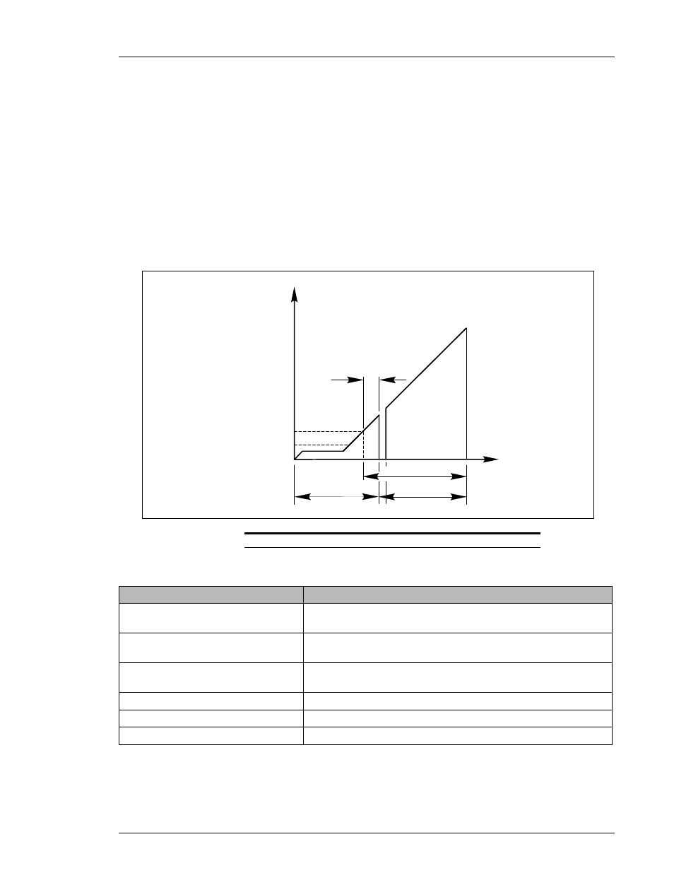
{ Two-Step Fastening
P The System fastening parameters must be configured according to the Engineered
fastening specification.
P Two-step fastening will be used primarily for joints that have a requirement to
synchronize with another spindle during the final stage of the rundown.
Examples: Connecting rod, main bearing cap, any multiple-spindle unit.
P The System will fasten to the 1st TORQUE/ANGLE during the specified 1ST STEP
time. Once either SPEED CHANGE TORQUE or 1st TORQUE/ANGLE is
reached, the System will switch to the specified TORQUE SPEED (Section 6.3).
When all fasteners have reached 1st TORQUE/ANGLE, the spindles will
synchronize and rotate simultaneously the specified number of degrees from
SNUG TORQUE to STD ANGLE within the specified FINAL STEP time.
STEP
TORQUE
FINAL
STEP
FINAL ANGLE
1ST
STEP
1ST
ANGLE
SNUG TORQUE
ANGLE
(TIME)
SPEED CHANGE
TORQUE
FIG. 6-1-2b Angle Control Functions for Two-Step Fastening
Chapter 6: Fastening Instructions (Rev. 1/98)
Page 6-5