3 load control – E-Mon E34-6003200R*KIT User Manual
Page 41
CLASS 3400 METER
41
62-0391-01
12.3 Load Control
The Class 3400 Load Control relay is used to activate alarming or load control. The
relay contacts are rated for 250 VAC and a maximum of 3 amps load. It can be used for
direct control of alarms under 3 amps or as a pilot duty device for high loads.
The relay set points are accessed through push buttons on the meter’s display board.
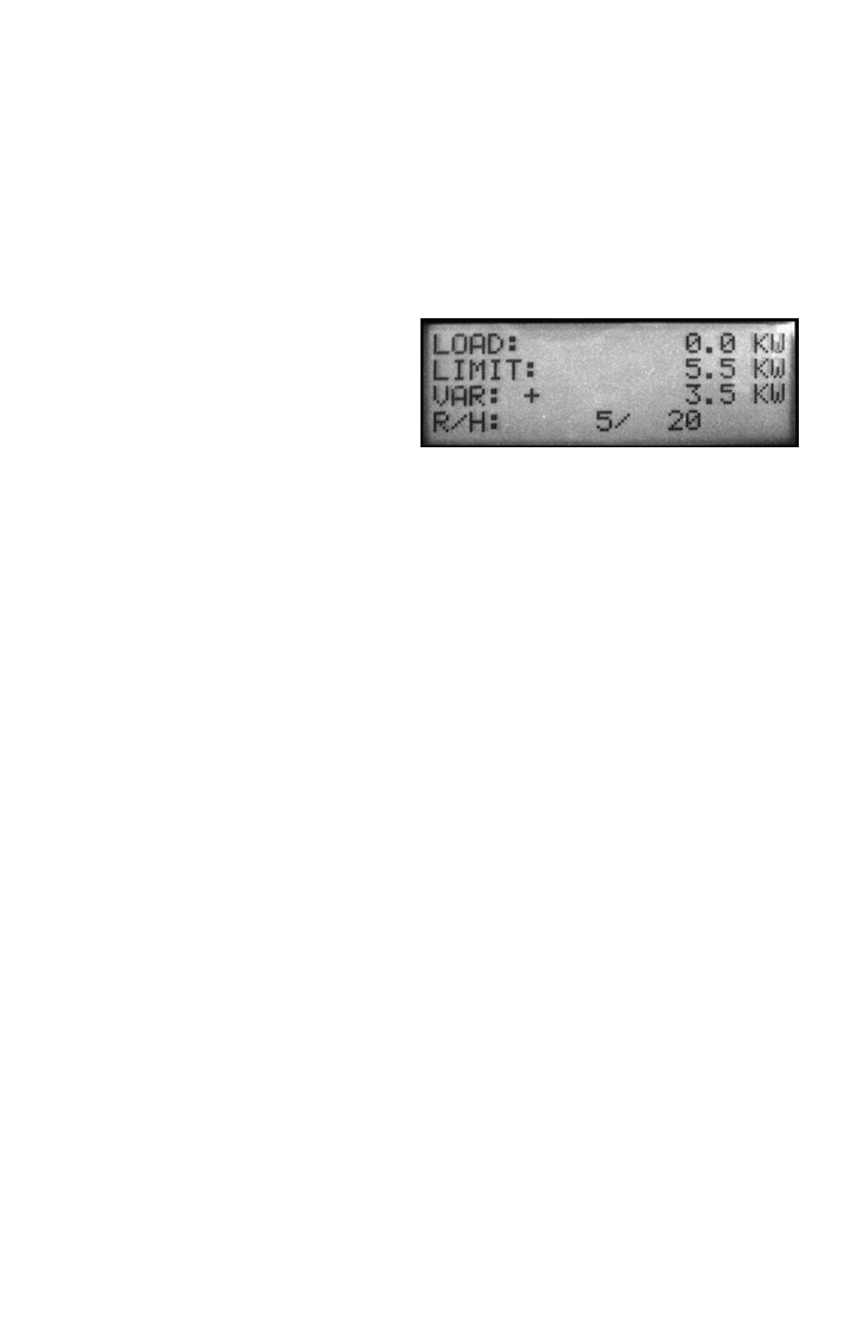
The meter’s display screen indicates the load settings.
a. LOAD: Present load on the
meter
b. LIMIT: Load Control set
point
c. VAR: Deactivation variation
d. R/H: Ramp and Hold set-
tings
Fig. 22. Load Control.
a. The present load (LOAD) on the meter indicates the actual KW load in real-
time.
b. The load control set point (LIMIT) is set to the desired point for the relay to
activate. Depending on the alarm/control requirements, this can be used for
either high or low load activation.
c. The relay deactivation setting (VAR) is the point where the relay is deacti-
vated. The “+” sign indicates that the deactivation point will occur when the
load rises above the set point. This is used when the relay is to be activated
on a low load condition. The “-” sign indicates that the deactivation point will
occur when the load drops below the set point. This is used when the relay is
to be activated on a high load condition. The kw setting indicates the differ-
ence from the set point where the relay will deactivate.
In the example above, the relay is set to activate on a low load condition. The relay will
deactivate when the load rises (+) above the set point by 3.5 kw. (deactivates at 9 kw).
d. The Ramp (R) setting indicates the time delay for activation when the set-
point is reached. This is to prevent relay function on short term load
changes, such as a motor start. The example shows a 5 second delay before
the relay activates.
The Hold (H) setting indicates the time delay for relay deactivation when the load
variation is reduced from the variation that was set. The example shows that there is a
20 second delay before the relay deactivates. This is designed to prevent short cycling
of loads when the relay functions.
Section 10.0 describes the pushbuttons and their functions.
- E34-6001600R*KIT E34-600800-R*KIT E34-600400-R*KIT E34-600200-R*KIT E34-600100-R*KIT E34-4803200R*KIT E34-4801600R*KIT E34-480800-R*KIT E34-480400-R*KIT E534-480200-R*KIT E34-480100-R*KIT E34-4003200R*KIT E34-4001600R*KIT E34-400800-R*KIT E34-400400-R*KIT E34-400200-R*KIT E34-400100-R*KIT E34-2083200R*KIT E34-2081600R*KIT E34-208800-R*KIT E34-208400-R*KIT E34-208200-R*KIT E34-208100-R*KIT