Introduction, Mode selector switch, Normal operating mode – Electronics International UBG-16 User Manual
Page 6
Introduction
Introduction
Introduction
Introduction
Introduction
Congratulations on purchasing the Ultimate Bar Graph Engine Analyzer (UBG), one of the most sophisticated
diagnostic tools available in general aviation. You can learn the basic operation of the UBG in the first few
minutes of hands-on operation. Although the UBG is simple to operate, its capabilities are numerous.
The UBG is shipped from the factory with all of the programmed limits turned off. This allows you to learn the
basic operation of the UBG without having to deal with alarms or programming limits. As you become comfort-
able operating the UBG, you can start using more of its features.
Mode Selector Switch:
Mode Selector Switch:
Mode Selector Switch:
Mode Selector Switch:
Mode Selector Switch:
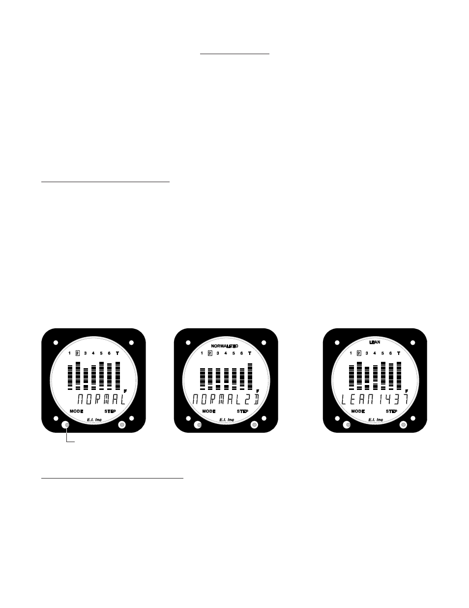
Each time the Mode Switch is pressed to the right, the UBG will advance to the next operating mode. There are
three modes of operation: Normal, Normalized and Lean. The top of the display will indicate in which mode the
UBG is operating. In the Normal Mode (figure 1), there is no indication at the top of the display. In the Normal-
ized Mode (figure 2), the word “NORMALIZED” appears at the top of the display, and in the Lean Mode (figure
3) the word “LEAN” appears.
Also, when switching between the three operating modes, “NORMAL”, NORMALZD” or “LEAN” appears in
the digital display when entering a mode, for as long as the Mode Switch is held to the right. This allows you to
see what mode the UBG is entering even if the top of the display is not visible.
The left position of the Mode Selector Switch is used for programming, which will be covered later in this
manual.
Normal Operating Mode:
Normal Operating Mode:
Normal Operating Mode:
Normal Operating Mode:
Normal Operating Mode:
In the Normal Operating Mode, the EGTs are indicated by the height of the lit bars in each of the columns. The
CHTs are indicated by the height of the blanked bars in each of the columns. A CHT of 300’F will cause the
second bar from the bottom to blank. The scaling of the blanked CHT bars is 33’F per bar.
3
Mode Switch
Mode Switch
Mode Switch
Mode Switch
Mode Switch
Figure 1
Figure 1
Figure 1
Figure 1
Figure 1
Figure 2
Figure 2
Figure 2
Figure 2
Figure 2
Figure 3
Figure 3
Figure 3
Figure 3
Figure 3