Input wiring, Output module wiring – Electro Cam EC-3400 Series User Manual
Page 8
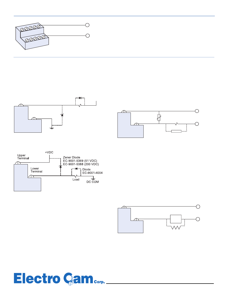
Figure 10 - Sinking
†
Output
Input Wiring
AC Output Module Wiring
AC output modules are wired with the load connected to the lower
terminal of the output module, while the external power supply is
connected to the upper terminal.
DC Output Module Wiring
DC output modules can be wired to sink
†
or source
†
load circuit.
The terminal block shown is for an EC-3004 unit or
EC-3404 unit. Other models will contain more blocks.
120 VAC
(108 to 132 VAC)
Output Module Wiring
Output modules act like switches; they do not supply power to loads.
Output modules available for the EC-3000 and EC-3400 Series units include DC, AC, and Reed Relay. An output module is required
for each output being used. Refer to page 4 for further module information. Module signals are isolated from one another, allowing AC
and DC modules to be mixed on the same control.
Most applications will function properly without the varistor or
R-C suppressor shown in the wiring diagram above. However,
when other switching devices are in series or parallel with the
AC output module, voltage spikes may damage the module. If
necessary, use one of the following two methods to suppress
voltage spikes.
• For infrequent switching, connect a varistor (MOV) across the
terminals.
• For continuous switching, connect an R-C suppressor in par-
allel with the load.
Most applications will function properly without the resistor shown
in the wiring diagram above. However, it may be necessary to
add the resistor if the load is affected by the module's off-state
leakage of 2 mA maximum. Keep in mind that a resistor across
a PLC input card may speed up the response time of that PLC
input.
Most applications will function properly without the diodes shown
in the wiring diagrams above. However, highly inductive DC loads
may damage modules by generating voltage spikes when
switched off. This type of inductive load may need to be sup-
pressed by a diode. If necessary, use one of the following two
methods to incorporate a diode into your circuit.
• Connect a Zener diode across the terminals. This will not sig-
nificantly increase the load turn-off time. The voltage rating of
the diode must be greater than the normal circuit voltage.
• Connect a reverse-biased diode across the load. This may
increase the load turn-off time.
Figure 11 - Sourcing
†
Output
Figure 9
Figure 12
Figure 13
13647 Metric Rd • Roscoe, IL 61073 USA • Web Site: www.electrocam.com • email: [email protected]
103 6/98
†
See page 2 for sinking/sourcing definitions.
L1
Upper Terminals
4
3
2
1
L2
9
8
7
6
Lower Terminals
Resistor EC-9001-5010
(5 Watt, 10K Ohm)
Load
Power
Supply
Upper
Terminal
Lower
Terminal
PLC
Input
Load
Upper
Terminal
Lower
Terminal
Load
Power
Supply
Varistor
EC-9001-1010 (120 VAC)
EC-9001-2020 (240 VAC)
R-C Suppressor
EC-9001-2000
(120 VAC or 240 VAC)
DC COM
Load
+VDC
Upper
Terminal
Lower
Terminal
Diode--EC-9001-4004
Zener Diode--
EC-9001-5369 (51 VDC)
EC-9001-5388 (200 VDC)