3004/3008/3012 layout drawings, Terminal and component identification – Electro Cam EC-3400 Series User Manual
Page 5
page 5
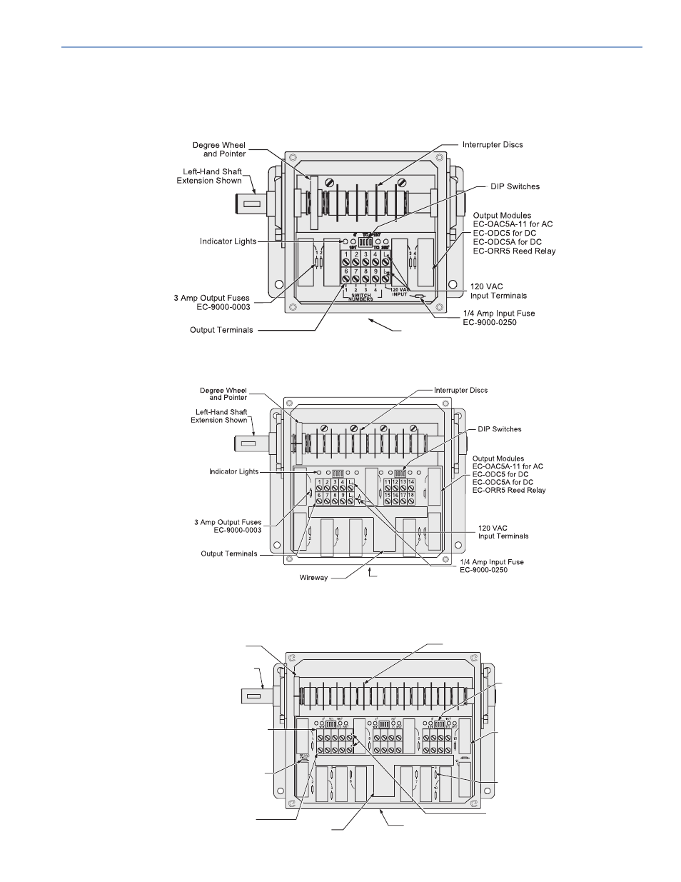
Figure 3
EC-3004 Unit
Figure 4
EC-3008 Unit
Figure 5
EC-3012 Unit
1 1/16" Dia. Hole
(For 3/4" Conduit)
1
5
1
6
0
°
to 180
°
5
0
°
to 180
°
181
°
to 360
°
181
°
to 360
°
1 1/16" Dia. Hole
(For 3/4" Conduit)
Degree Wheel
and Pointer
Left-Hand Shaft
Extension Shown
Indicator Lights
3 Amp Output Fuses
EC-9000-0003
Output Terminal s
120 VAC
Input Terminals
DIP Switches
Interrupter Discs
Wireway
Output Modules
EC-OAC5A-11 for AC
EC-ODC5 for DC
EC-ODC5A for DC
EC-ORR5 Reed Relay
1/4 Amp Input Fuse
EC-9000-0250
1 2 3 4 L
L
6 7 8 9
111213 14
15 16 1718
19 2021 22
26
25
24
23
1 1/16" Dia. Hole
(For 3/4" Conduit)
Terminal and Component Identification
The following three drawings are component layouts.
EC-3400 Series Units
All EC-3400 Series units have the same component layout as the EC-3000 Series units except a stainless steel double-
ended shaft extension and stainless steel enclosure with clamps to secure the cover are standard.