Teledyne 3300PB - Low cost percent oxygen analyzer User Manual
Page 19
3-3
Percent Oxygen Analyzer
Installation 3
Teledyne Analytical Instruments
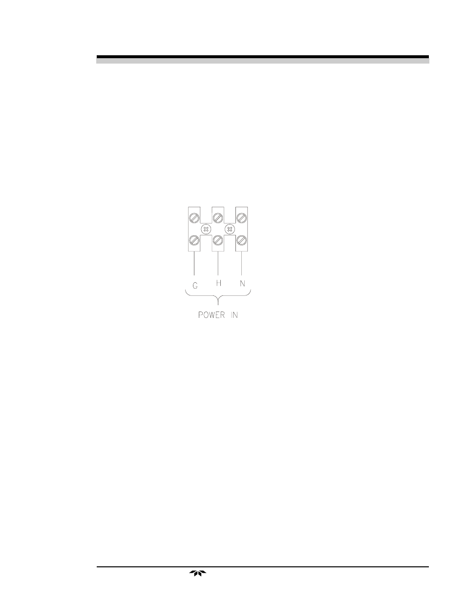
Primary Input Power: The power strip supplied inside the analyzer.
Connect ground to terminal 1, neutral to terminal 3, and hot to terminal 2.
Make sure female plug end is inserted in the control unit power receptacle.
The universal power supply allows direct connection to any 100-240
VAC, 50/60Hz power source. The fuse block, to the right of the power cord
receptacle, accepts two 5x20mm 0.5 A, 250V,time-lag (T) fuse. (See Fuse
Replacement in chapter 5, Maintenance.)
The Power switch is located on the right-hand end of the power source
input receptacle assembly.
AC Power Terminal Strip
Analog Outputs: There are three DC output signal connectors with
screw terminals on the panel. There are two wires per output with the polar-
ity noted. See Figure 3-3. The outputs are:
0–10 V % Range:
Voltage rises with increasing oxygen concentration,
from 0 V at 0 percent oxygen to 10 V at full scale
percent oxygen. (Full scale = 100% of programmed
range.)
0–10 V Range ID:
03.33 V = Low Range, 06.66 V = High Range,
10 V = Air Cal Range.
4–20 mA % Range:
Current increases with increasing oxygen concentra-
tion, from 4 mA at 0 percent oxygen to 20 mA at full
scale percent oxygen. (Full scale = 100% of pro-
grammed range.)
Alarm Relays: The three alarm-circuit connectors are screw terminals
for making connections to internal alarm relay contacts. There is one set of
contacts for each type of alarm. Contacts are Form C, with normally open
and normally closed contact connections capable of switching up to 0.5
ampere at 125 VAC into a resistive load (2A for 30 VDC).