Teledyne 3300PA - Low cost percent oxygen analyzer User Manual
Page 22
3 Installation
Model 3300
PA
3-6
Teledyne Analytical Instruments
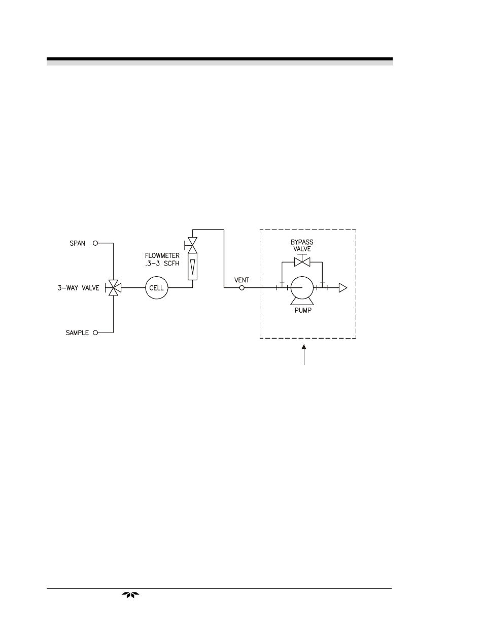
pump by-pass valve to limit the maximum flow rate to full scale on the
flowmeter with the flowmeter valve fully open. Adjust the analyzer flow
control valve (flowmeter valve) to a flow-rate of approximately 2 SCFH).
Select Span and verify that the span and Sample gas are at different pres-
sures. The calibration accuracy will be adversely affected if the Span and
Sample gases are at differing pressures.
If the span gas is provided from pressurized source, a control valve
must be added between the analyzer and the span gas source. This valve is
used to adjust the span flow rate to match the sample flow rate. Do not
adjust the span flow rate with the flow control valve located on the analyzer
for units with vacuum service options.
Figure 3-3: Piping Diagram for Vacuum Service Option
3.5
Installation Checklist
Before connecting the instrument to the power source and turning it on,
make sure you have:
•
Correctly installed the Sample and Exhaust gas lines
•
Opened the isolation valves
•
Checked for leaks
•
Set the sample pressure to 5–10 psig, nominal (for non-vacuum
service units)
•
Set the flow
Once the above checks have been made, you can connect to the power
source. The instrument is now ready for operation.
Customer Supplied Parts