Trace oxygen analyzer model 316ra/rb/rad/rbd – Teledyne 316RA / RB / RAD / RBD - Oxygen analyzers User Manual
Page 9
TELEDYNE ANALYTICAL INSTRUMENTS
5
Trace Oxygen Analyzer Model 316RA/RB/RAD/RBD
Location
The Series 316 Trace Oxygen Analyzer should be installed at viewing
level in a sheltered area. The analyzer case is not to be considered water
tight by the customer.
NOTE: Auxiliary heating MUST be provided in areas where the ambient
temperature drops below 32°F.
For the location and identification of the gas line, electrical connec-
tions, and physical dimensions of the analyzer, see the Outline Diagram
(RA: B-40393; RB: C-38551; RAD: B-40400).
After making the panel cutout, TAI suggests line drilling the mounting
holes using the analyzer case itself as a template.
Gas Line Connections
The sample inlet and outlet connections are:
RA:
¹/
8
" female N.P.T.
RB:
¹/
8
" tube fitting
RAD: ¹/
8
" female N.P.T.
TAI suggests using a Teflon sealing tape as a sealant rather than pipe
dope. Make sure that mating fittings are not cross-threaded before applying
force with wrench.
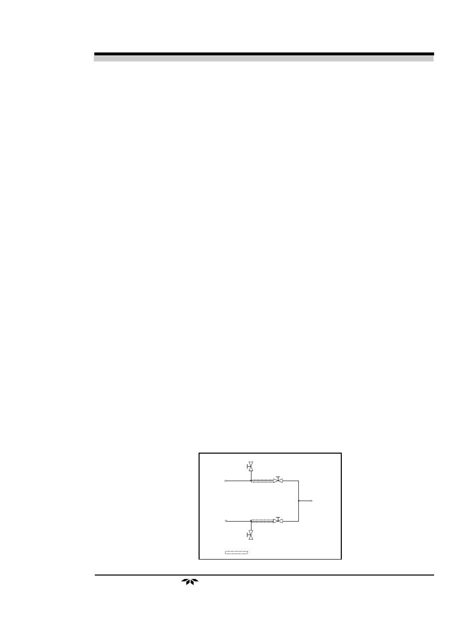
Input Selector Manifold (Optional)
A simple manifold is necessary to introduce either sample or calibra-
tion (span) gas into the analyzer. TAI recommends the manifold design
shown. Span purge and sample purge lines are necessary to flush oxygen
accumulated in the lines due to minute leaks. Just prior to switching to
either gas source, the respective purge valve should be opened for a short
period of time (10-30 seconds). Good quality, 2-way needle valves should
be used. Three-way valves may be used but are not recommended.
TO ANALYZER
INLET
SAM PLE IN
SPAN G AS
IN
SPAN
PURGE
= M INIM IZE LENG TH
SAM PLE
PURGE