Pump maintenance chart, Maintenance instructions, Force locking nut deflection retaining bolt – SPP Pumps Auto Prime Medium Head Open Set - ACE Range User Manual
Page 7
Operators Instructions for
ACE80/100 Diesel Driven Centrifugal Pumps
Manual No/Rev
W72-019E / 4
6. PUMP MAINTENANCE CHART
For engine maintenance periods refer to the engine operators handbook supplied with this manual.
PERIOD
TASK
Daily
Visually check for leaks.
Check for vibration.
Check the mechanical seal oil level and top up as required.
Weekly or
100 hrs
Check all fastener security.
Check the condition of the lifter bracket/frame and check the security of attachment to
the unit.
Check tension of vacuum pump drive belt.
6 monthly
or 1500 hrs
Check reflux ball is sealing on its seat.
Check and if necessary renew vacuum pump drive belt.
Dismantle and clean valve gear, tank, connecting pipes and priming tank.
Change mechanical seal oil.
Annually or
6000 hrs
Check vacuum pump blade condition
The above schedule is given for guidance but site operating conditions may override the suggested
maintenance intervals
.
7. MAINTENANCE INSTRUCTIONS
7.1 Mechanical Seal Oil Reservoir
Maintain the oil level between the maximum
and minimum levels marked on the dipstick.
7.2 Drive Belt Adjustment
7.2.1
Remove guard.
7.2.2
Slacken the locking nut and the retaining
bolt, rotate the tensioner to adjust the
tension of the belt. Tighten the locking nut
and the retaining bolt and check the tension
thus:
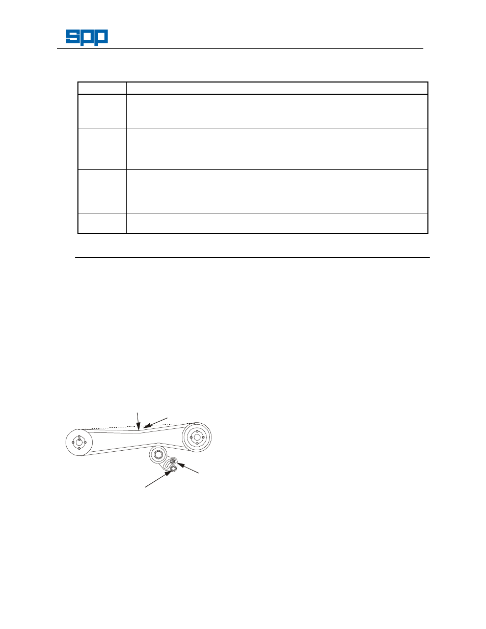
FORCE
LOCKING
NUT
DEFLECTION
RETAINING
BOLT
Belt Tensioning
7.2.3
V Belt tension is correct when the deflection
is 4mm with a force of 1.5kg applied at the
centre of the longest run.
Note: DO NOT OVERTIGHTEN BELTS
UNDER ANY CIRCUMSTANCES.
7.3 Mechanical Seals
7.3.1
Ensure that the coolant/lubricant level is
maintained. It is imperative that the seals
are never run dry. Immediate seal failure
will result.
7.3.2
Any contamination of the fluid should be
investigated immediately. Should a large
loss of fluid be experienced then the pump
must be stopped immediately.
7.3.3
Replacement of the seals is considered a
workshop operation where higher standards
of cleanliness can be maintained and the
specialised tooling required is more readily
available.
7.4 Mechanical Seal Removal
7.4.1
Remove the Tee piece and priming tank,
place oil tray under mechanical seal oil
drain plug to drain oil.
7.4.2
Remove the non-return valve and volute to
access the impeller. Unscrew impeller anti-
clockwise with the aid of a mallet until
undone, note the number of shims fitted
behind and retain for reuse.
7.4.3
Once the impeller is removed, remove the
rotating part of the primary mechanical seal
and remove rear wear plate. Then press
the seat out of the back wearplate.
7.4.4
Remove the circlip and washer off the shaft.
Then remove the secondary mechanical
seal and engine adaptor plate. Then press
out the seat.
7.4.5
Check the condition of the ’O’-rings and
replace if necessary.