Installation – Fulton VMP Hot Water (VMPW) User Manual
Page 20
© The Fulton Companies 2012
INSTALLATION
VMPW-IOM-2012-1001
SECTION 2
2-14
operating temperature. Check all local codes for requirements.
The fl ue must be as large or larger than the outlet on the vessel. Avoid fl ue
piping and elbows by placing the equipment as close as possible to the chimney.
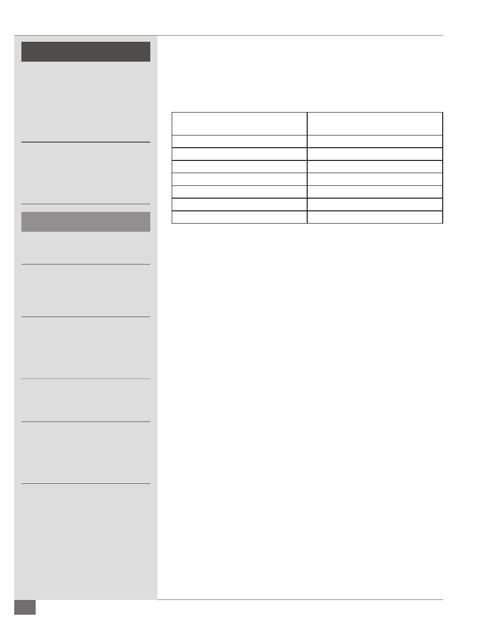
TABLE 4 - MINIMUM FLUE SIZES
Model
Minimum Flue Size
inches (mm)
40
12 (305)
50
12 (305)
60
12 (305)
80
14 (356)
100
14 (356)
130
14 (356)
150
16 (406)
Adhere to the following for stack and fl ue installation (see Figure 2):
1. Ensure the stack rises continuously to the connection at the chimney and
contains no more than two bends at 45 degree angles or less. If required,
as a result of space limitations, one 90 degree elbow (or tee) can be fi tted
at the back of the vessel.
2. Ensure 2 feet (0.6 m) of straight, horizontal fl ue before any change in
direction, fi tting or draft regulator. This is to prevent potential pilot or
main fl ame failures due to back pressure build up during ignition. Any
alternative stack arrangement must supply negative 0.02 to 0.04”wc.
3. Ensure the run in the total distance of stack ducting, as measured in a
straight line from the outlet of the boiler to the outlet of the stack, does
not exceed 25% of the rise. With the exception of the duct run previously
described, horizontal sections of ducting must be avoided and should not
exceed 4 feet (1.2 m) total. See Figure 2.
4. Ensure the stack, chimney, and any components associated with the stack,
such as heat reclaimers or assist fans, are constructed from material that is
rated for a 1000 F (538 C) operating temperature.
5. Ensure the stack and chimney material complies with all applicable codes.
6. Make adequate provisions for the support of the weight of the chimney
and stack to avoid having a load imparted to the outlet connection of the
equipment.
7. Ensure the draft, when fi ring, is negative and constant. A reading of -0.02
to -0.04”wc (-0.508 to -1.016 mm) when the unit and stack are cold usually
indicates suffi
cient draft. When the unit is running and the stack is hot, the
draft should read -0.04 to -0.08 “wc (-1.016 to -1.524 mm) negative.
8. The installation of a draft regulator by the client/contractor is
recommended at all installations. This will help to maintain the required
draft. The placement of the draft regulator should be as shown in Figure 3.
Insulate the section of the chimney duct within the building.
ã
WARNING
All information in this manual is for
reference and guidance purposes,
and does not substitute for required
professional training, conduct,
and strict adherence to applicable
jurisdictional/professional codes and
regulations.
Non-Fulton product information is for
reference purposes only. No Fulton
document may substitute for full
review of documentation available
from the component manufacturer.
Ð
CAUTION
Boilers damaged due to adverse water
conditions are not covered by warranty.
The weight of all piping must be
properly supported. Failure to support
piping may result in equipment
damage and/or system leakage.
Piping must take into consideration
potential for freezing interference and/
or damage as a result of expansion,
contraction, vibration, or other
movements.
Dirt, water, and/or other debris in the
piping system after welding may result
in equipment failure.
To maintain a reasonable
temperature in the equipment area
and ensure safety to personnel, the
section of the chimney duct within
the building should be insulated.