Installation, Utilities, The gas supply – Fulton VMP Hot Water (VMPW) User Manual
Page 12
© The Fulton Companies 2012
INSTALLATION
VMPW-IOM-2012-1001
SECTION 2
2-6
3. See Table 3 for minimum make up air openings required
for each model.
TABLE 3- MINIMUM MAKE UP AIR OPENING REQUIREMENTS
Model
Fresh Air Opening FT2 (M2)
40
1 (.09)
50
1 (.09)
60
1.5 (.14)
80
4 (.37)
100
4 (.37)
130
5 (.46)
150
7.5 (.69)
4. If positive forced ventilation is adopted, ensure that
there will be no appreciable pressure variation in the
equipment room.
5. Avoid ventilation which creates a negative pressure
in the building as it will seriously aff ect combustion
and proper operation of the burner. Please note that
exhaust fans or similar equipment can create a down
draft in the chimney or starve the burner’s air supply.
Either case may result in poor combustion or nuisance
failures. A properly designed make-up air system in the
equipment room will preclude these possibilities and is
required to maintain proper combustion.
6. Eliminate potential for high risk situations for particulate
matter to be in the combustion air supply (e.g., as a
result of construction and maintenance activities).
Utilities
The Gas Supply
Adhere to the following for gas supply installation:
1. Install gas piping in accordance with all applicable
codes.
2. Ensure pipe and fi ttings used are new and free of dirt or
other deposits.
3. Ensure piping is of the proper size for adequate gas
supply to the gas head assembly. Consult your gas
company for specifi c recommendations.
4. When making gas piping joints, use a sealing
compound resistant to the action of liquefi ed
petroleum gases. Do not use Tefl on tape on gas line
heads.
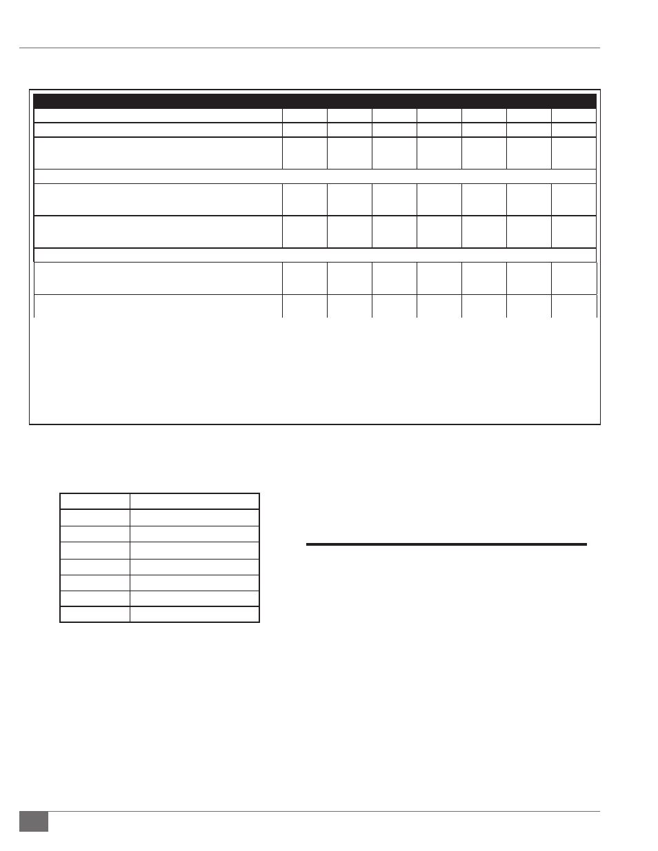
Model VMP-W Low Emissions (LE) MOTOR
Model VMP-WModel
40
50
60
80
100
130
150
Model VMP-W
40
50
60
80
100
130
150
Burner Motor **
HP
WaƩ s
5
3730
5
3730
5
3730
5
3730
5
3730
Consult
Factory
Consult
Factory
Approximate Weights
Shipping Weight
LB
KG
6575
2982
7373
3345
8170
3706
8800
3992
10300
4672
12800
5806
12800
5806
OperaƟ ng Weight
LB
KG
8659
3928
9684
4393
10671
4840
12051
5466
14700
6668
20585
9337
20585
9337
Approximate Fuel ConsumpƟ on at Rated Capacity+
Natural Gas
FT
3
M
3
1595
45
1992
56
2392
68
3188
90
3985
113
5182
147
5978
169
Required Gas Pressure (IN. W.C./PSIG)
Minimum/Maximum
30/10
30/10
40/10
40/10
40/10
60/10
60/10
208V, 60 CY, 3 Phase
16.7
16.7
16.7
16.7
24.2
Consult Factory
230V 60 CY 3 Phase
15.2
15.2
15.2
15.2
22
Consult Factory
460V 60 CY 3 Phase
7.6
7.6
7.6
7.6
11
Consult Factory
Specifi caƟ ons and dimensions are approximate. We reserve the right to change data without prior noƟ fi caƟ on.
Design condiƟ ons based on 160 F return and 180 F supply.
+ ConsumpƟ on based on natural gas 1000 Btu/Ō 3.
** Sub 20 ppm; for lower requirements, consult factory.