Computer system (via cam), Computer system, Via cam) – Adder Technology 5000 User Manual
Page 13: Computer, System
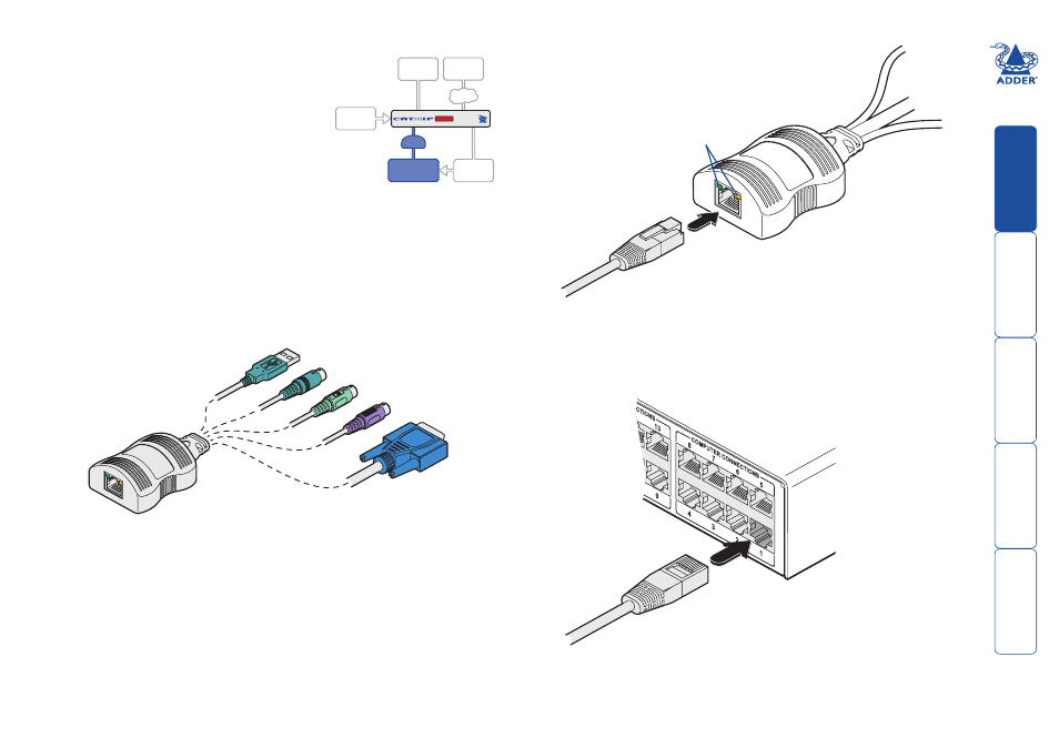
Computer system (via CAM)
Each computer system is connected to the
AdderView CATxIP 5000 unit via a Computer
Access Module (CAM) and standard category 5,
5e or 6 cabling. CAMs are available in various
formats to suit differing computer system types
and their particular connector styles.
Each CAM uses Adder Keep Alive technology
to ensure that the keyboard and mouse inputs
to the computer remain active, even when
the particular channel is not selected. This action ensures that there are no
connection delays or problems as the port is selected.
To connect a computer system
1 Ensure that power is disconnected from the AdderView CATxIP 5000 unit
and the system to be connected.
2 Locate the required CAM (there are three types available) and attach its
video, keyboard and mouse (PS/2-style, USB or Sun) to the relevant sockets
on the computer system.
3 Lay a suitable length of category 5, 5e or 6 cabling between the computer
system and the AdderView CATxIP 5000 unit. The maximum length of the
cable is 10 m (32 feet).
4 Attach the connector of the cable
run to the socket of the CAM.
5 At the other end of the cable run, attach the cable connector to one of the
sockets labelled
COMPUTER CONNECTIONS
on the rear panel of the AdderView
CATxIP 5000 unit.
Video
PS/2-style mouse
PS/2-style keyboard
USB keyboard/mouse
Sun keyboard/mouse
A range of different
connector combinations
are made available
across the five CAM
formats
Computer
Access
Module
Category , e or
cable from CAM
Category , e or
cable to AdderView
CATxIP 000
AdderView CATxIP
000 rear panel
Green indicator - power present
Yellow indicator - signal activity
Note: CAMs derive power from the
computer system via either the PS/2-style
keyboard connector, USB or SUN connector.
COMPUTER
SYSTEM
CAM
Note: Each CAM is
specifically shaped so
that it can be secured
using a cable tie around
its middle. In this way,
two CAMs can also be
neatly joined together,
back-to-back.