Pach and Company AeGIS 7000 Series Quick Guide User Manual
Page 2
1
2
3
4
5
6
7
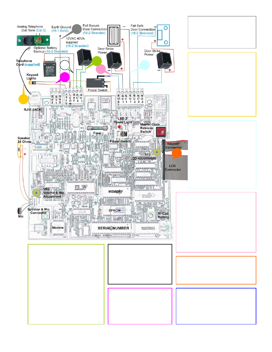
1. EARTH GROUND
16 gauge- single solid wire to
ground the system. If the
system has been struck by
lightning multiple times, try to
remove the earth ground.
2. TELEPHONE LINE
Cat 5 twisted pair (from the
telephone company dial
tone), maximum distance 200
feet. If you encounter static or
radio interference:
Remove the earth ground
Install a DSL filter in series
with the phone line.
Install RF filter
Contact the radio station,
they may have a solution
3. DOOR STRIKE/GATE
The system has two
independent on board relays
(125VAC 12A, 250VAC 7A,
and 30VDC 7A). 18 gauge 2-
conductors stranded wire for
each door. An isolation relay
with separate power supply is
recommended for magnetic-
lock. Installation to eliminate
spikes. See diagram for
wiring connections, also refer
to door strike or gate operator
owner’s manual.
4. POSTAL LOCK
Postal switch blue and yellow wires
are connected to the terminal pins
POST and LCOM
Postal input only works for relay 1.
Postal switch and knock-out are
provided. Call the local post office
for installing the postal lock
POST and LCOM input can also
be used for free exit switch, loop
detector or any device with dry
contact output.
5. POWER
12Vac 40VA supplied or 12Vdc
3A not supplied. Use at least 18
gauge 2 conductors stranded
wires for power.
The voltage
measurement must be in the
range of :
12.5Vac-14Vac--12Vac power
13.5Vdc-14Vdc-- 12Vdc power
Warning:
If you have low voltage
issue, do not use higher voltage
transformer or power supply, to do
so will damage the system.
Install surge protector (ASP1) or UPS
for power and telephone to protect the
system from power surges.
6. BATTERY BACKUP
Optional battery backup is
needed to keep the system
in operational during the
power outages. Use
ABAT1 (12Vdc 4.5Ahr, last
for 3-4 hours). Use 18
gauge 2 conductors
7. NIGHT LIGHTS
The night lights turn on
24/7, prewired to +12V and
LCOM.
Warning:
DO NOT USE
+12V and LCOM terminal
pins for input power.
8. KEYPAD AND LCD RIBBON
CABLE
Ribbon cables must be plugged in
as shown on diagram with the red
line dots are on top.
8
Prior removing the knock-out, any
drilling or grinding during the
installation removes the board.
Always turn the system off if you are
doing service.
Place ribbon cables on the side before
closing the panel’s door.