10 analog transmitter installation, 1 oct reed transmitter, 11 internal electronic transmitter installation – Orion Instruments Atlas User Manual
Page 13
46-638 Magnetic Liquid Level Indicators
13
1.10
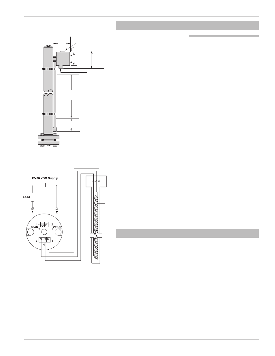
Analog Transmitter Installation
1.10.1 OCT Reed Transmitter
The OCT analog transmitter mounts directly to the side
of the Atlas or Gemini chamber, providing a continuous
4–20 mA output signal proportional to liquid level. Using
simple and reliable reed switches surface mounted to a
printed circuit board, the unit provides level accuracy of
±0.50" (13 mm).
The OCT reed transmitter is shipped attached to the MLI
gauge and is precalibrated to the customer specified span.
See Figure 10. Refer to Figure 11 for wire terminations for
the OCT.
Installation is simplified by utilizing gear clamps that can
be repositioned with a screw driver.
Caution: If the MLI is insulated, the analog transmitter probe must be
located outside of the insulation blanket.
NOTE: For supply connections, use wire with a minimum rating of
+167° F (+75° C) as required by process conditions. Use a
minimum of 14 AWG wire for power and ground field wires.
NOTE: Housing must be grounded via protective ground screw in the
base of the housing.
NOTE: It is the responsibility of the customer to comply with applicable
installation codes and practices. Class
I, Division 1 locations
may contain explosive gas mixtures. Appropriate precautions
must be taken. Installation should be performed by qualified
personnel.
Caution: In hazardous areas, do not power the unit until the conduit
is sealed and the enclosure cover is screwed down securely.
1.11
Internal Electronic Transmitter Installation
The Gemini Model enables the customer to install several
different types of either continuous measuring instruments
(transmitters) or point level control devices (switches). The
electronic instrument is installed in the 2" or 3" secondary
chamber of the Gemini MLI. The factory should be con-
sulted for these applications to review operating parameters
and to ensure that the desired instrument is properly
applied.
As the electronic instrument is supplied separately from
the Gemini MLI, the instruction manual for the electronic
unit should be carefully reviewed prior to installation in
the chamber. The instruction manual will be shipped with
the instrument.
4.0 (102) REF.
Inactive length
XXX = Span
active length
3.8 (140)
REF.
3.5 (90)
REF.
4.5 (115)
REF.
0.4 (10) REF.
Label bracket
3/4" NPT
conduit
connection
red
yellow
black
Resistor
Chain
Reed
Switch
Figure 11
black:
common connection of reed contacts
yellow: upper end of the resistor chain
red:
lower end of the resistor chain
Figure 10
inches (mm)