Vacuum leak test – Mityvac MV4525 COOLING SYSTEM TEST & REFILL KIT User Manual
Page 14
Vacuum Leak Test
For diagnosing:
Cooling system leaks
Notes
This equipment uses a venturi vacuum to perform a vacuum leak test.
The venturi requires clean, dry, high pressure air between 90 and 120
psi (5.5–10 bar) (550–1000 kpa) to create the vacuum.
Prior to testing, install a male quick-change air nipple with 1/4" NPT
male thread to the venturi.
The altitude at which the vacuum test is performed can significantly
affect the ability of the venturi to produce a vacuum. As the altitude
increases, the maximum vacuum the venturi can create will decrease.
This is normal and should not be considered a malfunction.
It is recommended that the cooling system be drained of coolant prior
to performing a vacuum leak test and automatic refill.
When connecting components using quick-connects, make sure the
sleeve snaps forward to lock the connection.
Set-up & Procedure:
1. Properly position the vehicle for service access to the radiator
or coolant bottle. Turn on the heater and set it to its highest
temperature setting.
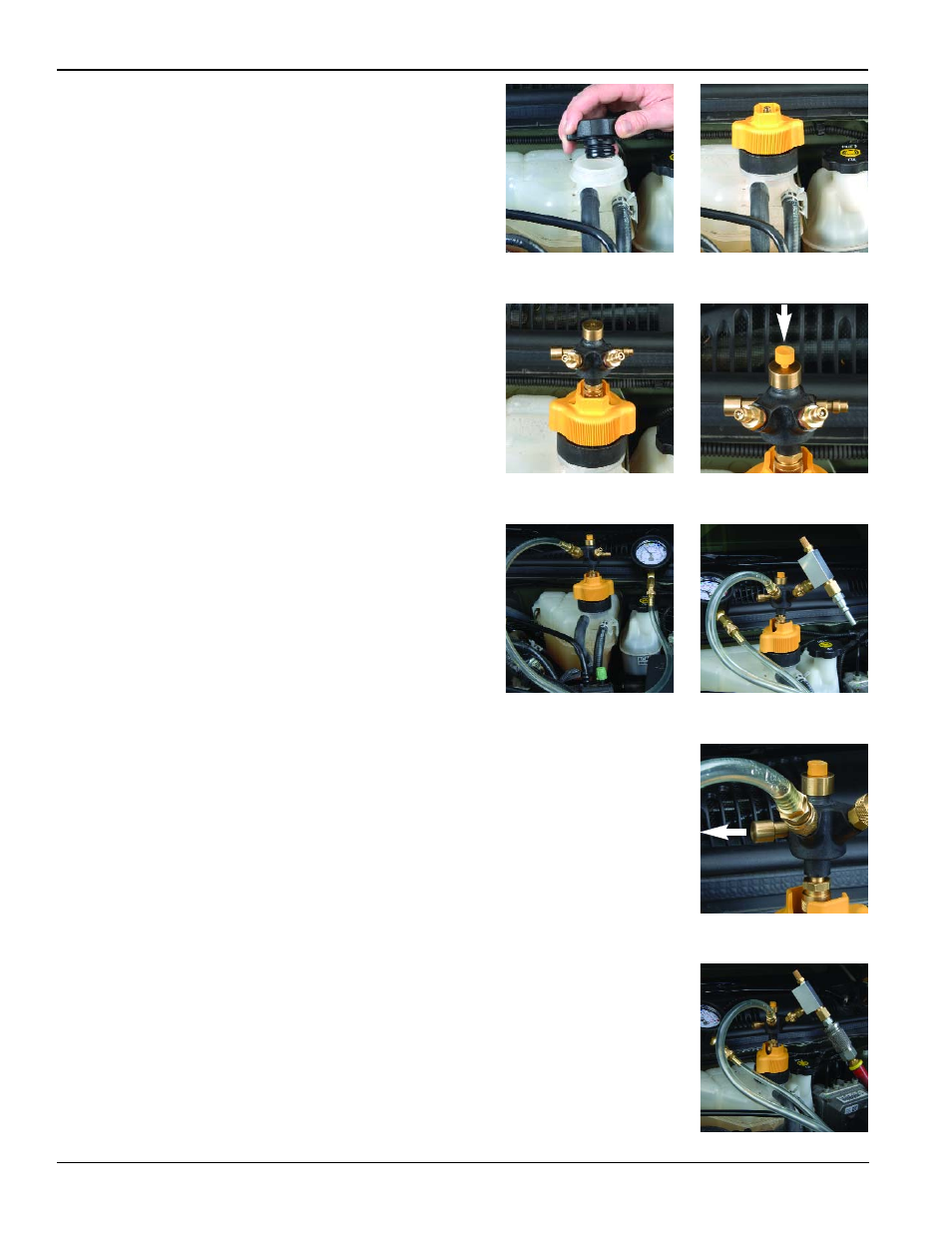
2. Ensure the cooling system is cool and not pressurized. Carefully
remove the radiator or coolant bottle pressure cap (Fig. 42).
3. Select the correct Cooling System Adapter for the application.
Refer to the Adapter Selection Guide included in the kit.
4. Apply water or coolant to the rubber gasket and/or o-ring on
the adapter, and install the adapter in place of the pressure
cap (Fig. 43).
5. Install the Valve Coupler onto the system adapter using the
quick-connect. Make sure the quick-connect sleeve snaps
forward to lock the connection (Fig. 44).
6. Install the Coupler Plug into the top of the Valve Coupler and
tighten the threaded cap securely to form an airtight seal (Fig. 45).
7. Connect the Compound Gauge to the male quick-connect
labeled “Gauge” extending from the Valve Coupler. Note: It may
be more convenient to install an Extension Hose between the
coupler and the gauge (Fig. 46).
8. Connect the Venturi Vacuum to the male quick-connect labeled
“Pressure/Vacuum” extending from the Valve Coupler. Note: It
may be more convenient to install an Extension Hose between
the coupler and the vacuum (Fig. 47).
9. Ensure the Shuttle Valve on the Valve Coupler is shifted to the
“Closed” position (Fig. 48).
10. Connect clean, dry, regulated compressed air between 90 and
120 psi (6.2 and 8.3 bar) (600 and 830 kPa) to the Venturi Vacuum
by means of the previously installed air nipple (Fig. 49).
11. Turn on the compressed air. The vacuum will make a hissing noise
as the high pressure air passes through it. If the cooling system is
not empty, it is normal that some fluid may be expelled from the
venturi exhaust.
continued on next page
Page Number - 14
Form 822947
Fig. 43
Fig. 45
Fig. 47
Fig. 49
Fig. 42
Fig. 44
Fig. 46
Fig. 48