Mityvac MV5565 FUEL INJECTION CLEANER User Manual
Page 13
Form 801817
Page Number - 13
Intake System Decarbonizing
(requires MVA550 Decarb Nozzle, sold separately)
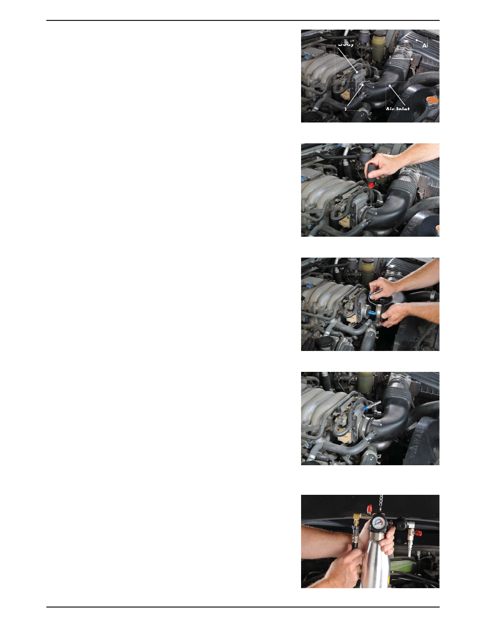
The Decarb Nozzle (MVA550) should be installed inside the
air intake duct, where it clamps to the inlet of the throttle
body. It must be installed downstream of the mass airflow
sensor (Fig. 13), so the cleaning solution does not come in
contact with the delicate sensor. In some cases, the mass
airflow sensor is mounted in the throttle body. Do not use the
Cleaner to perform air induction cleaning on this type of air
intake system.
The spray nozzle should point directly at the center of the
throttle plate without touching it. With the nozzle inserted into
the air stream, the small S-shaped steel tube should pass
between the air duct and the throttle body at the point where
the duct clamps onto the throttle body inlet. The supply hose
connection end of the nozzle assembly should extend outside
of the duct and the whole assembly held in place with the
worm clamp that secures the air duct to the throttle body. The
S-shaped steel tube can be bent into any shape required for
the installation.
1. Run the car until the engine is at operating temperature.
2. Place the vehicle transmission in park or neutral, apply
the parking brake, and turn off the key.
3. Loosen the clamp securing the air intake duct to the inlet
of the throttle body (Fig. 14).
4. Slide the air intake duct off the throttle body and the
install the Decarb Nozzle so the spray nozzle end is
aimed at the center of the throttle plate, but not
touching it (Fig. 15).
5. With the nozzle pointed at the throttle plate, bend and
position the S-shaped steel tube so the air intake duct
can be slipped over it (Fig. 16).
6. Secure the adapter in place by tightening the hose
clamp. For additional support and to ensure the
Decarb Nozzle remains in the proper position, an
extended clamp, part no. MVA551 is available for
separate purchase. See page 3 for additional details.
7. Unscrew the Cleaner canister bottle from the manifold
assembly and pour in the appropriate decarbonizing
solution.
8. Screw the canister back into the manifold assembly,
and hang the Cleaner under the vehicle’s hood using the
chain provided.
9. Close the Cleaner inlet and outlet valves.
10. Close the relief valve by turning it clockwise until tight.
11. Pull out on the regulator adjustment knob to unlock it,
and adjust the regulator to fully open by rotating the knob
counter-clockwise.
Figure 13
Figure 16
Figure 14
Figure 15
Throttle Body
Figure 17
Hose Clamp
Air
Filter
Inlet
Mass
Airflow
Sensor
Air Inlet Duct