Discontinued – Max Machinery 272-5X8 BIDIRECTIONAL TRANSMITTER (210_240 SERIES FLOW METERS) User Manual
Page 12
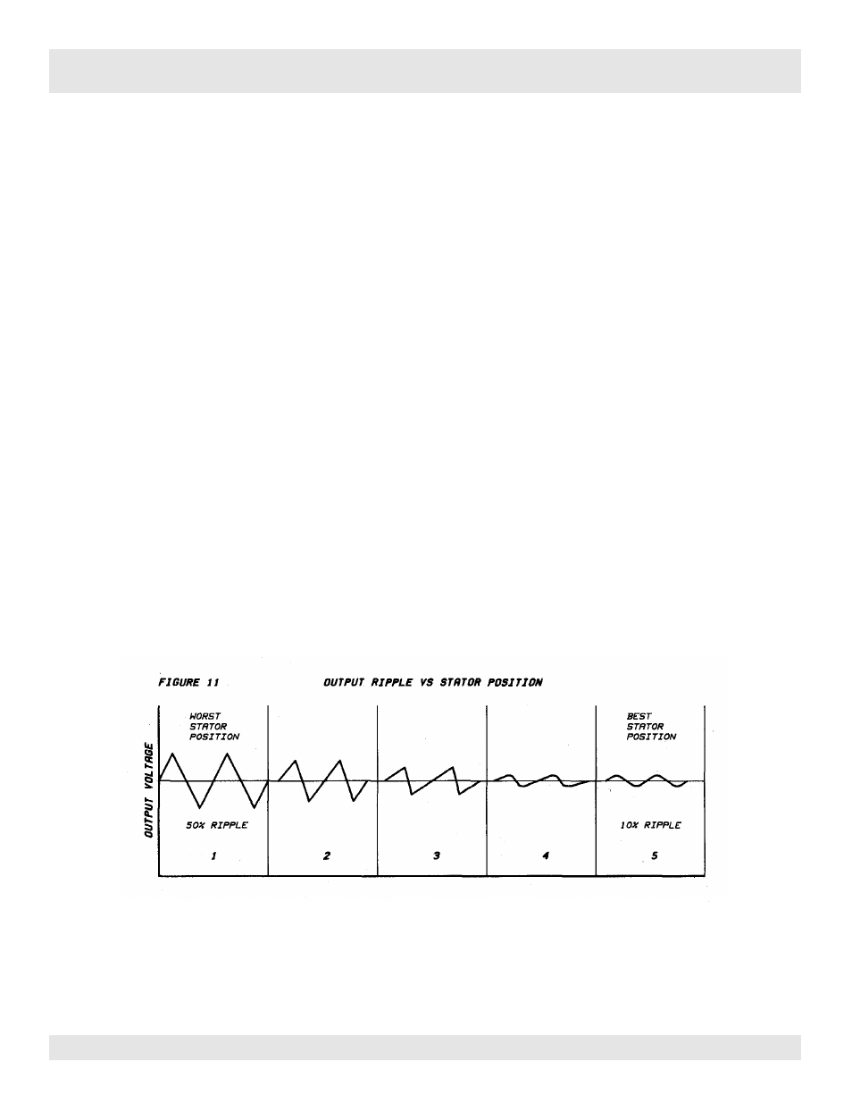
If this is not done, the electrical output of a meter and its transmitter will have as much as
50% ripple superimposed on the DC component of the output signal. The frequency of this
ripple will be four times the RPM of the meter. Such a situation will require more damping
than otherwise and will result in a slower responding system.
Ripple Adjustment Sensitivity: Increases and decreases the sensitivity of the ripple detection
circuit.
Ripple Indication : LED
Stator Adjustment Screw: Rotates the transmitter pickup coil.
The flow meter must have a flow through it for this adjustment to be useful. It is advisable to
adjust the ripple at the lower end of the flow range; although if the flow rate is less than 2% of
the flow meter ’s full scale capability you may have problems with this procedure. An oscillo-
scope attached to the output signal of the Model 272 can also be used.
Increase the Sensitivity Adjustment (cw) just until the Ripple LED next to it starts to turn on.
Then turn the Stator Adjustment Screw in a direction that decreases the brightness or turns off
the Ripple LED. Once again increase the Sensitivity potentiometer until the LED just comes on
and again turn the stator adjustment in a direction that minimizes the LED. Repeat this process
until any further change in the position of the stator screw causes the LED brightness to
increase rather than decrease.
The figure 11 shows the effect of the stator position on output ripple. There are four best and
four worst positions for the stator per revolution. This means that it will take a maximum of
45° on the Stator Adjustment Screw to find the best location.
Page 12
272-500-350 © 1996 (Rev. 8/00) Max Machinery, Inc.
USER OPTIONS AND ADJUSTMENTS
Discontinued