Agri-Fab 45-0351 User Manual
Page 5
5
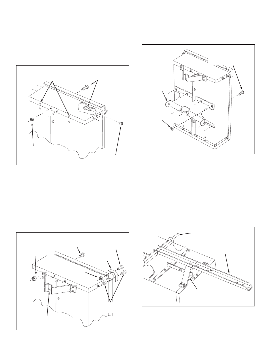
FIGure 5
FIGure 6
14. Assemble the wheel support to the cart using eight 5/16"
x 3/4" truss head bolts and 5/16" nylock nuts as shown
in figure 6. Heads of bolts go on the inside of the cart.
Tighten.
FIGure 4
FIGure 7
15. Lower the cart to rest upside down on its top flange with
the wheel support facing up. See figure 7.
16. Lay the drawbar tongue (open side facing up) onto the
Wheel Support and the Latch Stand Bracket. Slide the
axle through the wheel support and the tongue. See
figure 7.
AXLE
DRAW BAR
TONGUE
LATCH STAND
BRACKET
10. Assemble the front panel over the end of the cart using
six 1/4" x 5/8" hex bolts and 1/4" nylock nuts as shown
in figure 4. Leave two holes in the bottom of the panel
empty as shown. Pull the cart body halves together and
tighten the bolts in the bottom of the front panel, then
tighten the bolts in the sides. See figure 4.
11.
Tighten the bolts assembled in step 4 to fasten the
bottom of the cart together.
1/4" x 5/8"
HEX BOLTS
1/4" NYLOCK NUT
1/4" NYLOCK NUT
LEAVE HOLES OPEN FOR
LATCH STAND BRACKET
5/16"
NYLOCK
NUT
WHEEL
SUPPORT
5/16" x 3/4"
TRUSS HEAD BOLT
12. Assemble the latch stand bracket to the cart so that
the aligning tab is at the bottom of the bracket. Use four
1/4" x 5/8" hex bolts and 1/4" nylock nuts.
Tighten. See
figure 5.
13. Assemble a corner cap to each front corner using
one
or two 1/4" x 5/8" hex bolts and 1/4" nylock nuts per
cap.
leave out the rear bolt if the cart has top rails
(model 45-0350 only).
TIGHTen. See figure 5.
1/4" x 5/8"
HEX BOLT
LATCH STAND BRACKET
(Aligning tab at bottom)
1/4" x 5/8"
HEX BOLT
1/4" NYLOCK
NUT
CORNER
CAP
1/4" NYLOCK NUT
Leave out on
Model 45-0350