Reference diagram – Mach III Clutch T6H1G-STL, T6H1H-STL, T6H2H-STL User Manual
Page 2
7/9/2013
TORQLIM_FLEXCOUPL_MANUAL
Page 2 of 5
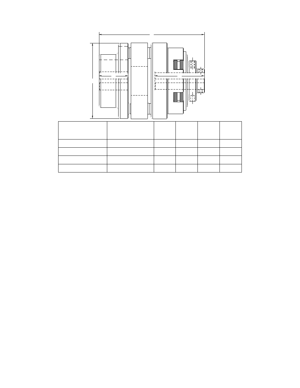
D
B
L
C
Reference Diagram:
I.
Torque Setting
Mach III torque limiters are typically shipped to the customer with the torque value they have
specified. (Note: All torque settings are +/- 10%.) If a torque limiter requires setting or re-
setting in the field, please refer to section VII of this document.
II.
Installation
A. SHAFT PREPARATION & MOUNTING
Mach III Clutch products are bored to fit a precision plug gauge for the specified bore size
and should slide fit the mating shaft. Make certain that the shaft is free of burrs or nicks. It
may be necessary to file or sand the shaft to assure a slide fit. Never hammer the torque
limiter onto the shaft. Hammering on the torque limiter may cause evident damage or subtle
injury that will shorten the wear life of the unit, and will void the warranty.
(1)
Apply the anti-seize (E-Z Break®) lubricant from the packet provided, or
equivalent, to the shaft.
(2)
Insert key (customer supplied) onto the shaft.
(3)
Slide torque limiter over key on the shaft, align the sprocket or pulley.
(4)
Tighten set screws to secure the torque limiter to the shaft.
B. FINAL INSPECTION & TESTING
After a short run, check set screws and alignment.
III. Operation:
This is a manually adjusted torque limiter. Torque is proportional to the amount of spring
compression.
Special Note Regarding Friction Disc Contamination:
The friction material used in this product will absorb oil, water, chemicals and other
contaminants. Depending on the type of contamination, torque limiter may either seize up
entirely or lose torque capacity. If friction discs become contaminated, they should be
replaced. See repair kit ordering information below.
Product#
MAX BORE
WITH
SQUARE
KEY
B
C
D
L
T3H2H-STL
0.875
1.
1.75
2.79
4.00
6.27
T4H2H-STL
1.125
2.06
3.50
5.13
7.44
T5H2H-STL
1.375
2.06
3.75
5.69
7.70
T6H1G-STL
2
2.37
4.25
7.34
9.91