Lightronics XC40 User Manual
Page 5
Page
5
of
16
XC-40 COMPACT DMX DIMMER
Version 0.3 OWNERS MANUAL 02/21/2008
www.lightronics.com
20080221
drp
Lightronics
Inc.
509
Central
Drive
Virginia
Beach,
VA
234354
757
486
3588
The channel levels will remain when you set them.
The control console can turn off the test setting by
raising the applicable channel fader to full then back
down. The channel test feature operates much like the
LOCAL mode. The difference is that local mode
LOCKS OUT all other control sources.
A usefull feature of the channel test mode is that the
display shows the current intensity level of the
channel regardless of the control signal source.
DIMMER SETUP
The dimmer setup menu (
dSEt
) enables you to set
several parameters which control how each individual
channel will operate. You can set a DMX address, set
a maximum intensity limit, and set a response curve.
Hold
MENU/NEXT for aprox. 5 sec. to access the
dimmer setup menu. The display will show
dSET
.
CHANNEL ADDRESSING (SOFTPATCHING)
In order to invoke the softpatching settings you must
first set the pack address (
PACA
) to
P000
. You
can set the channel DMX softpatch addresses at any
time but they will be ignored if
PACA
is not at
P000
.
TO SET CHANNEL SOFTPATCH ADDRESSES
Push
SELECT at the
dSEt
menu. The display will
toggle between the
dA-A
and the current DMX
address assignment number.
Use to set the desired DMX address (000 - 512)
for that channel. Push
SELECT to save the change.
Push
MENU/NEXT move to the next channel.
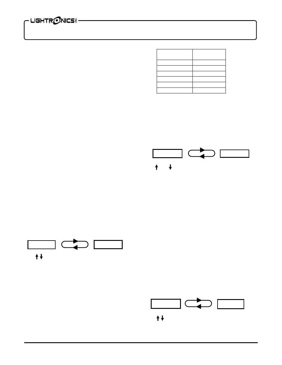
CHANNEL LIMITING
Each channel in the XC-40 can be set to limit the
maximum power applied to a channel. This feature
can lengthen the life of lamps and prevent premature
failures from power surges and high line voltage. The
following table gives the approximate XC-40 menu
setting for some typical limit percentage settings.
% MAX.
Intensity
Dimmer Limit
Setting
100 255
90 230
75 190
50 130
25 65
10 25
Note that limiting reduces the voltage applied to the
channel. The perceived light from the fixture will not
necessarily appear to track the limit setting in a linear
fashion.
Push
SELECT at the
dSEt
menu. Then push
MENU/NEXT until the display toggles between
dL-A
and the actual limit value
010 - 255
.
Use and to set the desired limiting value for that
channel. Push
SELECT to save the change.
Push
MENU/NEXT to advance to the next channel.
RESPONSE CURVE SELECTION
The XC-40 provides a selection of five response
curves to select from to accommodate a variety of
lamp and fixture types:
DIM:
Used for normal incandescent lamps.
RELAY:
Used for devices which cannot be dimmed or
for ON/OFF only control.
LED1 / LED2:
Two curve settings for LED fixtures.
FLUORESCENT:
For dimmable fluorescent ballasts
which can be used with a conventional dimmer.
These are sometimes referred to generically as "two
wire" ballasts.
Push
SELECT at the
dSEt
menu. Then push
MENU/NEXT until the display toggles between
dC-A
and the current curve setting.
Use to set the desired curve for that channel.
Push
SELECT to save the change.
d A - A
0 0 1
d L - A
2 5 5
d C - A
D i m