Lightronics XC40 User Manual
Page 12
Page
12
of
16
XC-40 COMPACT DMX DIMMER
Version 0.3 OWNERS MANUAL 02/21/2008
www.lightronics.com
20080221
drp
Lightronics
Inc.
509
Central
Drive
Virginia
Beach,
VA
234354
757
486
3588
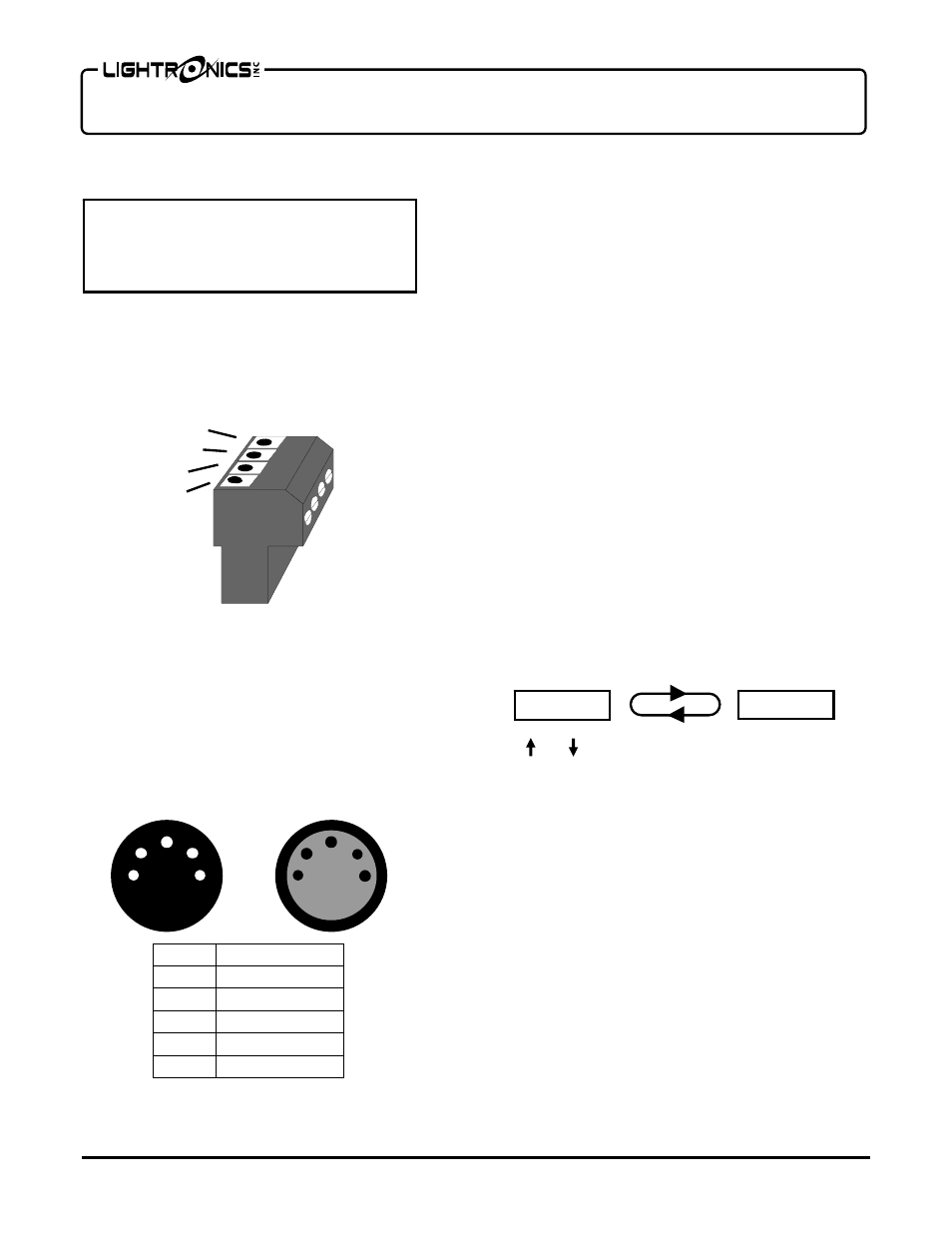
XC-40 AND SMART REMOTES CONNECTORS
SMART REMOTES CONNECTOR DETAILS
The diagram below shows the signals for the 4 Pin,
smart remotes connector.
XC-40 CONNECTOR DETAILS FOR REMOTE USE
The diagram below shows the signals for both of the
5 Pin XLR connectors when used with smart remotes.
UNIT ADDRESS ASSIGNMENT
The smart remote connection bus used with XC-40s
must have a single controlling (master) unit on it.
Assigning the master unit on the bus is accomplished
by setting unit addressess for the dimmers.
When using only one XC-40 with smart remotes
control, the unit must be set to UNIT ADDRESS 00.
If multiple XC-40s are used then one of them (and
ONLY one of them) must be set to UNIT ADDRESS
00. The remaining units may be set to any other unit
address. It is recommended that they be set to
consecutive numbers starting at 01 for future use.
TO SET THE UNIT ADDRESS
Hold
MENU/NEXT for aprox. 5 seconds to access
the menus. The display will show
dSET
.
Push
MENU/NEXT until the display shows
SYSt
.
Push
SELECT. The display will toggle between
CnFG
and the currently selected control source.
Push
MENU/NEXT until the display toggles
between
ArcU
and the current unit address number.
Use and to change the unit address number. Then
push
SELECT to save the selection.
Hold
MENU/NEXT for aprox. 5 seconds to exit
from the menus.
CREATING AND SAVING SCENES
Scenes to be activated by an XC-40 dimmer must first
be created and stored (recorded) in the dimmer pack.
Scene recording stores the current intensity levels of
all four channels in the unit regardless of how they
were set.
Intensity levels can be set using only the dimmer, in
the local mode, or by operating the unit with a DMX
console. Each scene created has an associated user
settable fade time.
CAUTION
REMOVE ALL POWER FROM THE XC-40
BEFORE MAKING OR CHANGING SMART
REMOTE CONNECTIONS.
1
2
3
4
REMOTE COMMON
REMOTE DATA -
REMOTE DATA +
REMOTE V+
1
2
3
4
5
1
2
3
4
5
MALE
5 PIN
XLR
FEMALE
5 PIN
XLR
REMOTE COMMON
REMOTE DATA -
REMOTE DATA +
NOT USED
REMOTE V +
SIGNAL
PIN #
1
2
3
4
5
A r c U
0 0