P a c a – Lightronics XC40 User Manual
Page 4
Page
4
of
16
XC-40 COMPACT DMX DIMMER
Version 0.3 OWNERS MANUAL 02/21/2008
www.lightronics.com
20080221
drp
Lightronics
Inc.
509
Central
Drive
Virginia
Beach,
VA
234354
757
486
3588
OPERATION
SETUP AND OPERATING CONFIGURATION
All operating functions and settings for the XC-40 are
menu controlled using the LED Display and the 4
buttons located near it on the back surface of the unit.
FACTORY DEFAULT CONFIGURATION
The XC-40 is supplied with a factory default setup
configuration. The unit may be reset to this condition
by keeping the
SELECT button held down while
power is applied. The display briefly shows
FACt
while the reset is being performed. The XC-40 is set
as follows when a reset is performed:
1. The unit is set for DMX (
5Pin
) operation.
2. The DMX pack address (
PACA
) will be set to
address 1 (
P001
).
3. Softpatch is set to DMX addresses 1 - 4
4. All channels curves are set for incandescent
dimming
(
Dim
).
5. Channel limiting is turned off (
255
).
6. Chase functions are set as follows:
Pattern
#:
01
Rate:
004
(1 sec. per step)
Fade:
050
(%)
Brightness:
100
(%)
7. The architectural Unit ID is set to
01
8. Power type is set to AUTO
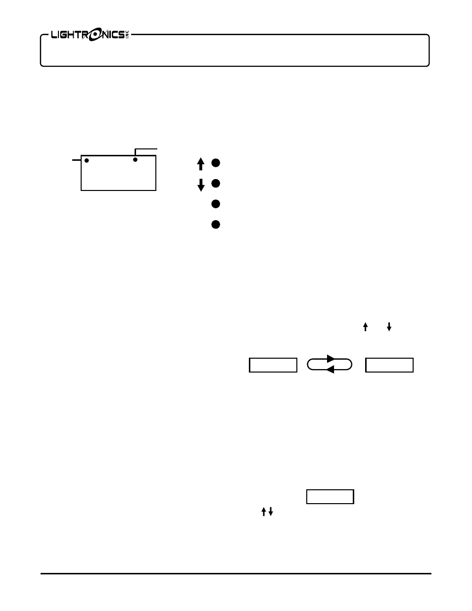
DISPLAY STATUS INDICATORS
The LED display shows a dot near the upper left
corner when a valid DMX signal is being received.
If equipped with the wireless option, another dot at the
top of the display indicates the status of an active
wireless link.
MENU ACCESS AND USE
Hold the
MENU/NEXT button down for aprox. 5
seconds to gain access to the complete menu system.
If there is no button activity for 1 minute while inside
the menus then the unit will revert back to the normal
display (
PACA
).
To exit from anywhere in the menus - Hold down
MENU/NEXT for aprox. 5 seconds. The unit will
revert back to the normal display (
PACA
).
A flow diagram of menu/display operation is provided
at the back of this manual.
QUICK PACK ADDRESSING
The XC-40 has a quick DMX address setup which
enables you to set the starting address of the pack (the
address for channel "A") without accessing the rest of
the menu system. When this is used, the remaining 3
channels ("B", "C", and "D") are set to the next
consecutive addresses.
During normal operation the LED display toggles
back and forth between
PACA
and the current pack
address such as
P001
. Use the and buttons
to set different pack address. Push
SELECT
to
save the setting when done.
If you set the pack address to
P000
then the unit
will run in soft patch mode. In this mode you can set
ANY channel of the pack (A - D) to ANY DMX
address (000-512) by using the dimmer setup (
dSEt)
menus. See
CHANNEL ADDRESSING
for details.
CHANNEL TEST
You can test the operation of each dimmer channel by
pushing
MENU/NEXT. The display will show the
intensity of channel A (00 - 99%) as shown below.
Use to adjust the intensity to the desired level.
Push
MENU/NEXT to advance to the next channel
(Channel B). The dimmer will return to its normal
display when you go past the last channel.
P A C A
MENU
NEXT
SELECT
DMX VALID
WIRELESS
STATUS
PACA
P001
A - 0 0