Vs-3 & vs-4 valves - disassembling, Disassembling the valve – Liquid Controls V-15, V-30, VS-3, and VS-4 Valves User Manual
Page 14
14
VS-3 & VS-4 Valves - Disassembling
The VS-3 & VS-4 Valves are under pressure from the
compression spring. The safest method for opening the
valve for service or maintenance is to place the valve on
a flat surface with the valve outlet facing down.
1.
Loosen the four bolts (Item 611) located on the valve
cap (Item 124). The compression spring will exert a
force on the cap and push it up.
2.
When the four bolts are almost completely removed,
check to see if the compression spring is still exerting
a force on the cap. If not, remove the four bolts and
washers completely. If there is still force on the cap,
remove two screws from opposite sides of the cap.
While bracing the cap with one hand, remove the
other two bolts and carefully release the cap until
the compression spring exerts no force.
3.
Note the orientation of the cap and valve handle.
Remove the cap (Item 124). The internal
components are attached to the cap and will come
out of the valve housing with the cap.
4.
To disassemble the cap assembly, it will be necessary
to remove the four cotter pins which hold the cup
(Item 133) to the links on each side of the cup. This
is only necessary when replacing the compression
spring or the cup.
5.
To replace the dashpot washer (Item 727), remove
the retaining ring (Item 559) from the end of the guide
shaft.
6.
Four screws (Item 627) and lock washers (Item 745)
secure the guide (Item 138) and seals in place.
These screws are accessed from the opening
created when the cap (Item 124) and components
were removed. Remove these four screws and
washers to inspect and replace components as
necessary.
The valve shaft (Item 368) is very difficult to remove, but
it is not necessary to remove it in order to inspect or
replace the O-Rings and bearings of the valve shaft.
7.
Remove the retaining ring (Item 564) from one side
of the valve shaft.
8.
Remove the shaft seal (Item 270), the bearing (Item
140) the O-Ring (Item 456), the inner bearing (Item
260) and the O-Ring (Item 451).
9.
Inspect and replace these components as needed.
10. Repeat steps 7-9 for the other side of the valve shaft.
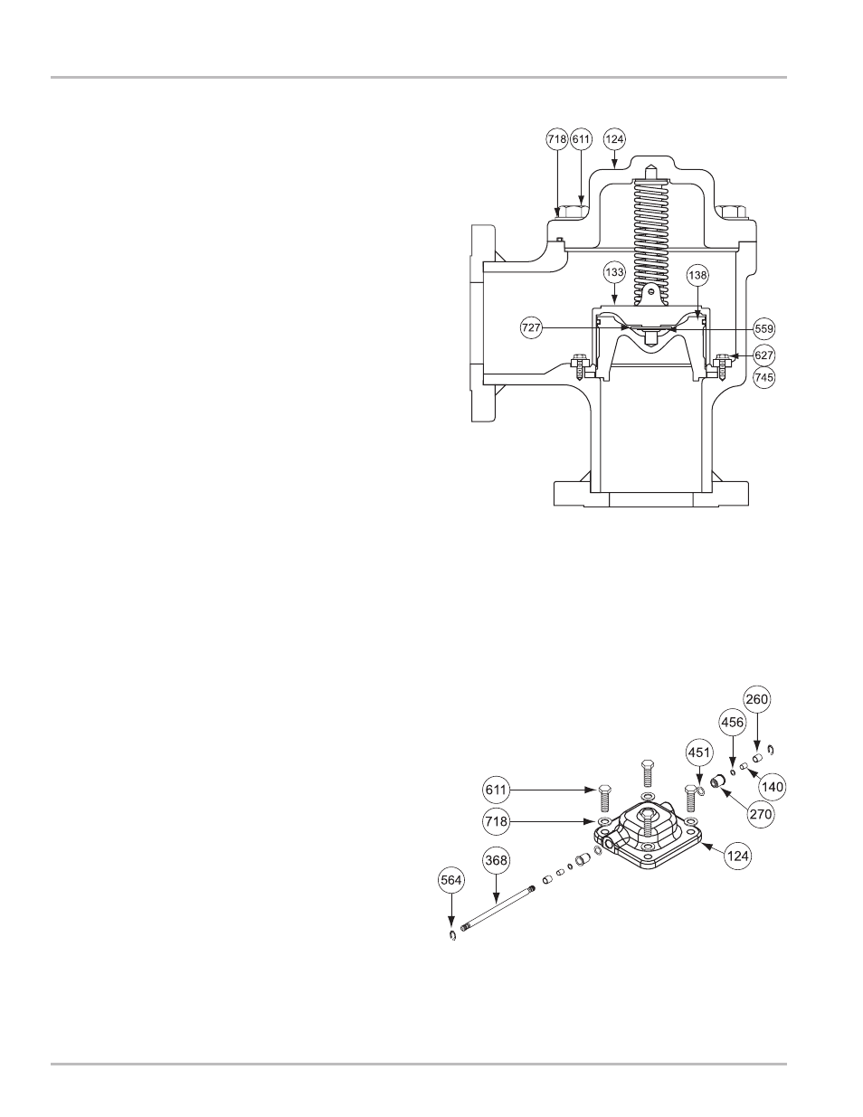
Disassembling the Valve
Figure 18: VS-3 Valve
Figure 19: VS-3 Cap Assembly