Assembly/installation, Montaje/instalación – Level Mount MC55 User Manual
Page 8
8
8
www.levelmount.com
1-888-229-1459
EU: +0044 844 567 2657
UK: 0844 567 2657
©2011 Level Mount - Patents Pending
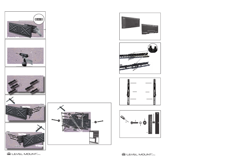
Option B – If the Wall is Concrete
Caution: Due to the weight of the TV Mount/Wall Plate, it may be necessary
to have a helper hold the Mount while marking and attaching to the
wall.
To attach the Wall Plate to concrete, place the Wall Plate at the desired height.
Mark 3 holes on the Right side of the Wall Plate with a pencil when the Wall
Plate is level indicated by the Built-in Bubble Level/Spirit Level as shown in
Figure 13. Push the TV Mount over to the right and repeat on the left side of
the Wall Plate.
Set the TV Mount/Wall Plate to the side. Drill 6 holes into the concrete, where
marked, as shown in Figure 14. When drilling the holes for the Concrete
Anchors (Bag 6) into the concrete, use an electric drill with a 12mm masonry
bit.
Caution: Do not use a hammer drill, which would break out and weaken the
concrete.
Insert the 6 Concrete Anchors (Bag 6) into the holes and set them flush to the
concrete wall by tapping them in with a hammer as shown in Figure 15.
To attach the Wall Plate to the concrete wall, use a Hex Nut Wrench to drive
in 6 Hex Screws and Washers (Bag 6) into each of the Concrete Anchors
through the Wall Plate as shown in Figure 16A and 16B. Screw tightly enough
to produce a strong bond, but do not over-tighten or there may be damage to
the mount or screws.
Caution: Due to the weight of the TV, it is essential that all 6 screws (Bag 6)
be used when mounting the Wall Plate to the wall.
Assembly/Installation
Figure 13
Built-in Bubble Level/
Built-in Bubble Level/
Spirit Level
Spirit Level
Figure 14
Figure 15
Concrete Wall
Concrete Wall
Concrete Anchors
Concrete Anchors
Figure 16A
Hex Nut Wrench
Concrete Wall
Concrete Wall
Drill
Drill
Masonry Drill Bit
Masonry Drill Bit
12mm
12mm
Concrete Wall
Figure 16B
Hex Nut Wrench
Wall Plate
TV Mount
Right
Side
Left
Side
Concrete W
Concrete Wa
Concrete Wall
F
Wall Plate
Wall Plate
TV Mount
TV Mount
TV Mount
TV Mount
Wall Plate
Wall Plate
Wall Plate
n
TV Moun
TV Mount
(LM85MC Shown)
(LM85MC Shown)
(LM85MC Shown)
Note For DMC65 & MC65 Mounts – Attaching the Wall
Plate
In attaching the DMC65 or MC65 mount to the concrete wall, it is recommended
that eight screws be used as shown in Figure 16C.
Figure 16C
Hex Nut
Wrench
(DMC65 Shown)
Hex
Screws
Washers
x
e
x
H
ex
H
H x
e
H
H
H
He
x
Hex
x
x
x
x
x
x
x
x
x
x
x
x
e
He
He
H
x
x
x
x
x
e
He
He
He
He
He
He
He
He
x
x
x
x
x
Wall Plate
Wall Plate
TV Mount
TV Mount
This Hex Screw and
Washer attach to the Wall
Plate under the TV Mount
This Hex Screw and
Washer attach to the Wall
Plate under the TV Mount
Image shows Wall
Plate without TV
Mount attached
(It does NOT
come like this,
the TV Mount
is permanently
attached!) to
illustrate the four
layers of holes
for Hex Screw
attachment.
Washers
Washers
W
Wall
21
21
www.levelmount.com
1-888-229-1459
EU: +0044 844 567 2657
UK: 0844 567 2657
©2011 Level Mount - Patents Pending
Brazos de
extensión
superiores
Brazos de
extensión
inferiores
Brazos fijo o
giratorio
Montaje/Instalación
Paso 1 – Escoja el soporte correcto en función de la parte
trasera de su televisor
Antes de empezar la instalación, compruebe si la parte trasera de su televisor es
plana o hueca, tal y como muestra la Imagen 1. Si la parte trasera de su televi-
sor es hueca, es posible que necesita utilizar los separadores (Bolsa 5), tal y como
muestran las Imágenes 4 y 6. Los separadores sirven para rellenar el hueco que
queda en la parte trasera de su televisor, de manera que el soporte quede perfecta-
mente fijado a la parte trasera de su televisor.
Respaldo plano
Respaldo hueco
Imagen 1
Paso 2 – Instalación del Brazo de Extensión (en caso necesario)
Si los agujeros del brazo de extensión no están alineados con los agujeros de la
parte trasera de su televisor, no taladre ningún otro agujero. En lugar de ello, siga
estas instrucciones para instalar el brazo de extensión. En caso contrario, vaya
directamente al Paso 3.
Paso 2a – Fijar el Brazo de Extensión a los Brazos Fijos o
Giratorios
Fije el Brazo de Extensión a los Brazos Fijos o Giratorios utilizándolas siguientes her-
ramientas, tal y como muestra la Imagen 2:
•
Tornillos M5 (Bolsa 7)
•
Arandelas de presión M5 (Bolsa 7)
• Brazo
de
extensión
•
Brazo fijo o giratorio
•
Tuerca hexagonal M5 (Bolsa 7)
Ajuste el tornillo de la Imagen 2 para mover los brazos de extensión de manera que
queden alineados con los agujeros de la parte trasera de su televisor de pantalla
plana.
Paso 2b – Fijación completa del Brazo de Extensión
Los 4 Brazos de Extensión deberían estar fijados de la misma forma. Una vez termi-
nado, sus brazos fijos o giratorios junto con los brazos de extensión deberían tener el
aspecto de las Imágenes 3.
Imagen 2
Brazos de extensión
inferiores
M5 Tornillo
Brazos de extensión
superiores
Brazos d
Brazos de extens
inferiores
M5 Tornillo
p
Tornillo
Tuerca hexagonal
Arandela de presión
M5 Tornillo
Imagen 3
(Brazos Fijos Muestran)
Arandelas
Destornillador
Phillips
Brazo de extensión
Arandelas de presión
M4/M5/M6/M8
Tornillo M4,
M5 , M6 o M8
Separadores
Utilice el separador sólo en caso de que la parte
trasera de su televisor sea hueca
Imagen 4
Paso 2c – Fijar los Brazos de Extensión a la parte trasera del
televisor
Este paquete incluye tornillos de distintos tamaños que encontrará en las Bolsas 1
a 5. Por favor, asegúrese de utilizar el tamaño de tornillo adecuado para su televisor.
Los televisores pequeños necesitan las siguientes herramientas: (Para la mayoría de
televisores menores de 50’’ o 127 cm)
• Tornillo M4 (Bolsa 1) o Tornillo M5 (Bolsa 2)
• Arandelas de presión M4 (Bolsa 1) o arandelas de presión M5 (Bolsa 2)
• Arandelas 20 mm x 5.5 mm x 1,0 mm (Bolsa 5)
• Es posible que necesite una arandela adicional para evitar que la cabeza del
tornillo se incruste en la parte trasera del televisor
• Brazo de extensión
• Separador (Bolsa 5) Sólo en caso de que la parte trasera de su televisor sea
hueca.