Montaje/instalación, Assembly/installation – Level Mount MC55 User Manual
Page 7
22
22
www.levelmount.com
1-888-229-1459
EU: +0044 844 567 2657
UK: 0844 567 2657
©2011 Level Mount - Patents Pending
Imagen 5
Televisor
Televisor
de pantalla
de pantalla
plana
plana
Brazo de
Brazo de
extensión
extensión
inferior
inferior
Brazo de
Brazo de
extensión
extensión
superior
superior
Tornillo
Tornillo
Brazo fijo
Tornillo
Tornillo
Montaje/Instalación
Imagen 6
Utilice el separador sólo en caso de que la
parte trasera de su televisor sea hueca
Tornillo M4, M5,
M6/M8
Arandelas de presión
M4/M5/M6/M8
Arandelas
Televisor
de pantalla
plana
Brazo fijo o
giratorio
Separa dores
Separa dores
Destornillador
Phillips
Imagen 7
Televisor
Televisor
de pantalla
de pantalla
plana
plana
Tornillo
Tornillo
Tornillo
Tornillo
Paso 2c – Fijar los Brazos de Extensión a la parte trasera del
televisor (Continuó)
Los televisores grandes necesitan las siguientes herramientas: (Para la mayoría
de televisores mayores de 50’’ o 127 cm)
• Tornillo M6 (Bolsa 3) o Tornillo M8 (Bolsa 4)
• Arandelas de presión M6 (Bolsa 3) o arandelas de presión M8 (Bolsa 4)
• Brazo de extensión
• Separador (Bolsa 5) Sólo en caso de que la parte trasera de su televisor sea
hueca.
Para fijar los Brazos de Extensión a la parte trasera de su televisor, coloque los
2 tornillos de cada brazo en los agujeros del Brazo de Extensión y atorníllelos
con cuidado a la parte trasera de su televisor. Si encuentra resistencia, saque
de inmediato el tornillo y escoja otro tamaño que entre fácilmente y permita fijar
el tornillo de manera segura. Apriete bien los tornillos a la parte trasera de su
televisor, tal y como muestran las Imágenes 5.
Cuidado:
Apriete los tornillos sólo hasta que estén seguros, con
cuidado de no pasarse de rosca.
Paso 3 – Fijar los Brazos Fijos o Giratorios (sin Brazos de
Extensión) a la parte trasera de su televisor
Este paquete incluye tornillos de distintos tamaños que encontrará en las Bolsas
1 a 5. Por favor, asegúrese de utilizar el tamaño de tornillo adecuado para su
televisor.
Los televisores pequeños necesitan las siguientes herramientas: (Para la
mayoría de televisores menores de 50’’ o 127 cm)
• Tornillo M4 (Bolsa 1) o Tornillo M5 (Bolsa 2)
• Arandelas de presión M4 (Bolsa 1) o arandelas de presión M5 (Bolsa 2)
• Arandelas 20 mm x 5.5 mm x 1,0 mm (Bolsa 5)
• Es posible que necesite una arandela adicional para evitar que la cabeza del
tornillo se incruste en la parte trasera del televisor
• Brazo fijo, giratorio o voladizo
• Separador (Bolsa 5) Sólo en caso de que la parte trasera de su televisor sea
hueca.
Los televisores grandes necesitan las siguientes herramientas: (Para la mayoría
de televisores mayores de 50’’ o 127 cm)
• Tornillo M6 (Bolsa 3) o Tornillo M8 (Bolsa 4)
• Arandelas de presión M6 (Bolsa 3) o arandelas de presión M8 (Bolsa 4)
• Brazo fijo, giratorio o voladizo
• Separador (Bolsa 5) Sólo en caso de que la parte trasera de su televisor sea
hueca.
Para fijar los brazos fijos o giratorios a la parte trasera de su televisor, coloque
los 2 tornillos de cada brazo en los agujeros del brazo fijo o giratorio y apriételos
con cuidado en los agujeros de la parte trasera de su televisor. Si encuentra
resistencia, saque de inmediato el tornillo y escoja otro tamaño que entre
fácilmente y permita fijar el tornillo de manera segura. Apriete bien los tornillos a
la parte trasera de su televisor, tal y como muestran las Imágenes 7.
Cuidado:
Apriete los tornillos sólo hasta que estén seguros, con cuidado
de no pasarse de rosca.
(Brazos Fijos Muestran)
(Brazos Fijos Muestran)
Brazo fijo
Brazo fijo
o Giratorios
o Giratorios
7
7
www.levelmount.com
1-888-229-1459
EU: +0044 844 567 2657
UK: 0844 567 2657
©2011 Level Mount - Patents Pending
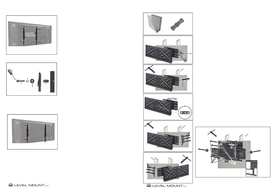
Step 4 – Attaching the Wall Plate to the Wall
Caution: Due to the weight of the TV Mount/Wall Plate, it may be necessary to
have a helper hold the Mount while marking and attaching to the wall.
Option A – If the Wall is Drywall
To attach the Wall Plate to drywall, locate two wooden studs using a Stud Finder
as shown in Figure 8. After you have determined the spot where you believe the
center of each stud to be (using the Stud Finder), hammer a small nail into that
spot far enough to confirm that you are hammering into solid wood (and not
something less dense, like particle board); remove the nail when done.
Pull the TV Mount Plate away from the Wall plate to get a clear view of the Wall
Plate. Line up the right top hole of the Wall Plate with the stud center marked on
the wall at the desired height. Then, use a pencil to mark the wall through the
top right hole in the Wall Plate over the center of the stud on the right side of the
Wall Plate as shown in Figure 9.
To attach the Wall Plate to the wall, drill a 3mm pilot hole where the top right
pencil mark was made. Using a Hex Nut Wrench, drive 1 Hex Screw with
Washer (Bag 6) through the one of the top right slots in the Wall Plate and
through the drywall into the stud as shown in Figure 10.
Once the top right screw is secure, adjust the Wall Plate until it is level using the
Built-in Bubble Level/Spirit Level as shown in Figure 11. With a pencil, mark the
desired location for the 2 remaining holes in the center of the stud on the right
side of the Wall Plate. Push the TV Mount Plate over to the right and repeat the
procedure in the center of the stud on the left side of the Wall Plate. Drill the 5
remaining holes with a 3mm drill bit where marked.
Using a Hex Nut Wrench, drive in the additional 5 Hex Screws and Washers (Bag
6) to secure the Wall Plate to the wall as shown in Figure 12A and 12B. Screw
tightly enough to produce a strong bond, but do not over-tighten or there may be
damage to the mount or screws.
Caution: Due to the weight of the TV it is essential to mount the Wall Plate to at
least 2 wooden studs and that all 6 screws be used when mounting the
Wall Plate to the wall.
Figure 8
Drywall with Exposed Studs
Stud Finder
Assembly/Installation
Figure 9
Drywall Stud
Figure 10
Drywall Stud
Hex Nut
Wrench
Figure 12A
Hex Nut
Wrench
Figure 11
Built-in
Built-in
Bubble Level/
Spirit Level
Wall Plate
Wall Plate
Drywall Stud
TV Mount
TV Mount
Figure 12B
Hex Nut
Wrench
Right
Side
Left
Side
Washer
a
sh
Hex
Screw
Wall Plate
Wall Plate
TV Mount
TV Mount
Figure 11
B
TV Mount
TV Mount
ght
de
Washers
Hex
Screws
TV Mount
TV Mount
Drywall Stud
Left
Side
Washers
Hex
Screws
TV Mount
TV Mount
(LM85MC Shown)
(LM85MC Shown)
(LM85MC Shown)
(LM85MC Shown)
(LM85MC Shown)
Figure 12C
Hex Nut
Wrench
Drywall Stud
Hex
Screws
Washers
x
e
x
H
ex
H
H x
e
H
ex
H
H
H
He
x
x
x
x
x
x
x
x
e
He
He
H
x
x
x
x
e
e
He
He
He
He
He
He
He
He
x
x
x
x
x
x
Wall Plate
Wall Plate
Note For DMC65 & MC65 Mounts – Attaching the Wall
Plate
In attaching the DMC65 or MC65 mount to the wall, it is recommended that eight
screws be used as shown in Figure 12C.
TV Mount
TV Mount
This Hex Screw and
Washer attach to the Wall
Plate under the TV Mount
This Hex Screw and
Washer attach to the Wall
Plate under the TV Mount
Image shows Wall
Plate without TV
Mount attached
(It does NOT
come like this,
the TV Mount
is permanently
attached!) to
illustrate the four
layers of holes
for Hex Screw
attachment.
Wash
sh
sh
W
Wa
h
sh
Wall Plate
Wall Plate
her
s
sh
sh
sh
h
h
h
e
e
Wall Plate
Wall Plate
(DMC65 Shown)