Montaje/instalación, Assembly/installation, Figure 4 – Level Mount DC65T User Manual
Page 7: Figure 6, Figure 7, Figure 5
26
26
www.levelmount.com
1-888-229-1459
EU: +0044 844 567 2657
UK: 0844 567 2657
©2011 Level Mount - Patents Pending
Montaje/Instalación
Figure 12
Paso 4 – Fijar la placa de soporte a la pared
Opción A – Si las paredes son de pladur
Para fijar la placa de soporte a una pared de pladur, localice las estructuras de
madera con un detector de madera. Cuando haya encontrado el lugar donde
crea que está el centro de la estructura de madera (utilizando el Detector de
Madera), clave un clavito en el hueco lo suficiente para confirmar que está
clavando sobre madera sólida (y no en algo menos denso, como una tabla de
aglomerado); una vez realizado, vuelva a quitar el clavito.
Alinee el agujero superior izquierdo de la Placa de soporte con el centro de la
estructura de madera que haya marcado en la pared, a la altura deseada. Utilice
un lápiz para marcar la pared a través del agujero superior izquierdo de la Placa
de soporte sobre el centro de la estructura, tal y como muestra la Imagen 9.
Para fijar la Placa de soporte a la pared, taladre un agujero guía de 4 mm sobre
el lugar marcado con el lápiz. Utilizando la llave hexagonal, atornille 1 tornillo
hexagonal con arandela (Bolsa 6) por el agujero superior izquierdo de la Placa
de soporte, atravesando la pared de pladur hasta llegar a la estructura de
madera, tal y como muestra la Imagen 10.
Una vez fijado el tornillo superior izquierdo, ajuste la Placa de Soporte usando
el Nivel de burbuja que viene incorporado o el nivel, hasta que la Placa esté
nivelada, tal y como muestra la Imagen 11. Marque con un lápiz los 3 agujeros
restantes. Taladre los 3 agujeros que acaba de marcar con una broca de 4 mm.
Utilizando la llave hexagonal, atornille los otros 3 tornillos hexagonales con
arandelas (Bolsa 6) para fijar la Placa de soporte a la pared, tal y como muestra
la Imagen 12. Atornille bien, hasta que quede fijo, pero con cuidado de no
pasarse de rosca, pues de lo contrario podría dañar el soporte o los tornillos.
Cuidado:
Debido al peso del televisor de pantalla plana, es fundamental
montar la Placa de soporte en al menos 2 estructuras de
madera, y que utilice los 4 tornillos para fijar la Placa a la
pared.
Imagen 10
Imagen 9
Imagen 11
Imagen 8
Pladur con estructuras visibles
Detector
de Madera
Nivel de burbuja
incorporado/
Nivel
Estructura de
Pladur
Placa de soporte
Placa de soporte
Placa de soporte
Placa de soporte
Estructura de
Pladur
Llave hexagonal
Arandelas
Tornillo
hexagonal
Placa de soporte
Placa de soporte
Estructura de Pladur
Tornillo
hexagonal
Placa de soporte
Llave hexagonal
Arandelas
Arandelas
e
e
e
la
l
la
la
la
s
s
s
P a
P
P
Pl
Pl
P
a
7
7
www.levelmount.com
1-888-229-1459
EU: +0044 844 567 2657
UK: 0844 567 2657
©2011 Level Mount - Patents Pending
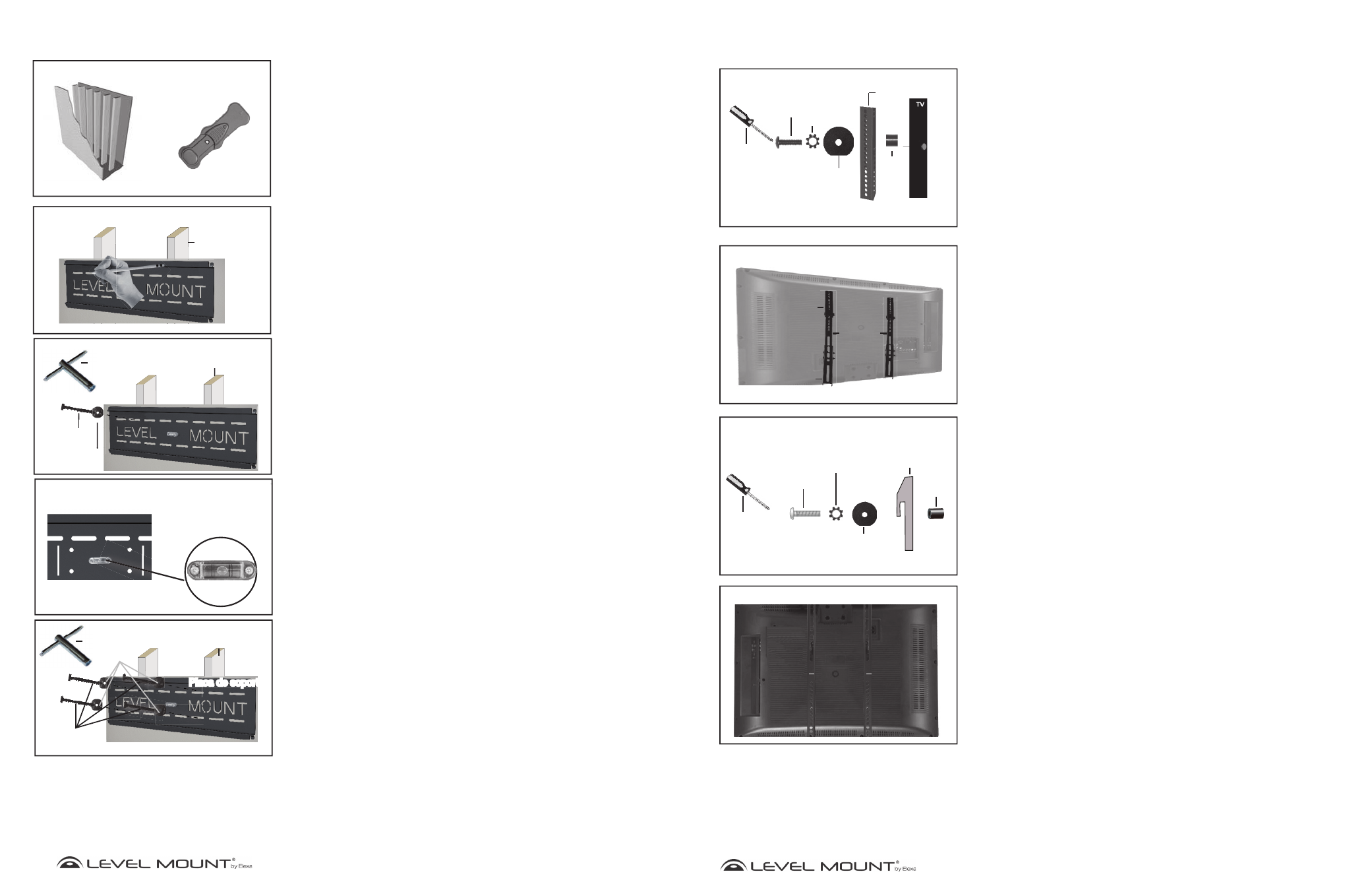
Step 3 – Attaching the Fixed or Tilt TV Arms to Back of TV
There are bolts of varying lengths included in this package, located in (Bags 1 through
5). Please use the bolt with the appropriate length for your TV.
Small TVs need the following hardware: (For most TVs under 50’’ or 127cm) (Figure 7)
• Bolt M4 (Bag 1) or Bolt M5 (Bag 2)
• Lock Washer M4 (Bag 1) or Lock Washer M5 (Bag 2)
• Washer 19mm x 5.3mm x 1.2mm (Bag 5)
• An additional Washer may be needed to prevent the bolt head from recessing into
the back of the TV
• Fixed or Tilt Arm
• Spacer (Bag 5) Only needed if the TV has a recessed back.
Large TVs need the following hardware: (For most TVs over 50’’ or 127cm) (Figure 7)
• Bolt M6 (Bag 3) or Bolt M8 (Bag 4)
• Lock Washer M6 (Bag 3) or Lock Washer M8 (Bag 4)
• Fixed or Tilt Arm
• Spacer (Bag 5) Only needed if the TV has a recessed back.
To attach the TV arms to the back of the TV, place the 2 bolts for each arm through the
holes of the TV Arms and carefully thread them into the holes in the back of the TV. If
there is any resistance remove the bolt immediately and select the correctly sized bolt
that enables a secure and snug fit. Tighten the bolts snugly to the back of the TV as
shown in Figure 7.
Caution:
Only tighten bolts until they are secure, do not over-tighten.
Assembly/Installation
Figure 4
Only use Spacer if TV has a recessed back
Extension Arm
Washer
19.05mm x 5.3mm x 1.2mm
M4/M5/M6
or M8 Lock
Washer
M4/M5/M6
or M8 Bolt
Phillips
Screwdriver
Spacer
k
S
Step 2c - Attaching Extension Arms to the back of the TV
Small TVs need the following hardware: (For most TVs under 50’’ or 127cm)
• Bolt M4 (Bag 1) or Bolt M5 (Bag 2)
• Lock Washer M4 (Bag 1) or Lock Washer M5 (Bag 2)
• Washer 19.05mm x 5.3mm x 1.2mm (Bag 5)
• An additional Washer may be needed to prevent the bolt head from recessing into
the back of the TV
• Extension
Arm
• Spacer (Bag 5) The spacers are only needed if TV has a recessed back.
Large TVs need the following hardware: (For most TVs over 50’’ or 127cm)
• Bolt M6 (Bag 3) or Bolt M8 (Bag 4)
• Lock Washer M6 (Bag 3) or Lock Washer M8 (Bag 4)
• Extension
Arm
• Spacer (Bag 5) The spacers are only needed if TV has a recessed back.
To attach the TV arms to the back of the TV, place the 2 bolts for each arm through the
holes of the TV Arms and carefully thread them into the holes in the back of the TV. If
there is any resistance remove the bolt immediately and select the correctly sized bolt
that enables a secure and snug fit. Tighten the bolts snugly to the back of the TV as
shown in Figure 5.
Figure 6
Only use Spacer if TV has a recessed back.
M4/M5/M6/
M8 Bolt
M4/M5/M6/M8
Lock Washer
Washer
19mm x 5.3mm x 1.2mm
Fixed or
Tilt Arm
Spacer
Phillips
Screwdriver
Figure 7
Flat Back TV
Fixed/Tilt Arms
Fixed/Tilt Arms
Figure 5
TV
Upper
Extension Arms
Lower
Extension Arms
Fixed or
Tilt Arms