Assembly/installation, Montaje/instalación, Step 2b - completed extension arm attachment – Level Mount DC65T User Manual
Page 6: Figure 2, Figure 3, Opción b – si las paredes son de hormigón
6
6
www.levelmount.com
1-888-229-1459
EU: +0044 844 567 2657
UK: 0844 567 2657
©2011 Level Mount - Patents Pending
Step 1 – Selecting the Correct Hardware Based on TV Back
Before beginning the installation, determine if the TV has a flat back or a recessed back
as shown in Figure 1. If you have a recessed back TV you may need to use the spacers
(Bag 5) as shown in Figure 4 or Figure 6. The spacer is used to fill the recessed area of the
TV so that the TV Bracket is fully supported and flush with the back of the TV.
Assembly/Installation
Flat Back
Recessed Back
Figure 1
Step 2 - Extension Arm Installation (if needed)
If the holes in the Fixed or Tilt Arms do not line up with the holes in back of the TV, do not
drill. Instead, follow these instructions for the Extension Arm Installation. Otherwise, skip
to Step 3.
Note: When using the Fixed Arms, the Extension Arms can be used for TVs with
VESA vertical hole placement that is greater than 370mm; and when using the
Tilt Arms, the Extension Arms can be used for TVs with a VESA vertical hole
placement that is greater than 500mm. Your TV manual/product labels should
specify the VESA hole spacing.
Step 2b - Completed Extension Arm Attachment
All 4 Extension Arms should be attached in the same manner. When completed, your
Fixed or Tilt Arms, with the Extension Arms attached, should appear as shown in the
photo in Figure 3.
Step 2a - Attaching Extension Arms to Fixed or Tilt Arms
Attach the Extension Arms to the Fixed or Tilt Arms using the following hardware as shown
in Figure 2:
• Bolts M5 (Bag 7)
• Lock Washer M5 (Bag 7)
• Extension
Arm
• Fixed or Tilt Arm
• Nut M5 (Bag 7)
Adjust the screws in Figure 2 to move the extension arms to align with the holes on the
back of the TV.
Figure 2
Extension Arm
Fixed/Tilt Arm
M5 Lock Washer
M5 Lock Washer
M5 Hex Nut
M5 Hex Nut
M5 Bolt
M5 Bolt
Figure 3
Lower Extension Arms
Upper Extension Arms
Fixed or Tilt
Arms
Fixed or Tilt
Arms
27
27
www.levelmount.com
1-888-229-1459
EU: +0044 844 567 2657
UK: 0844 567 2657
©2011 Level Mount - Patents Pending
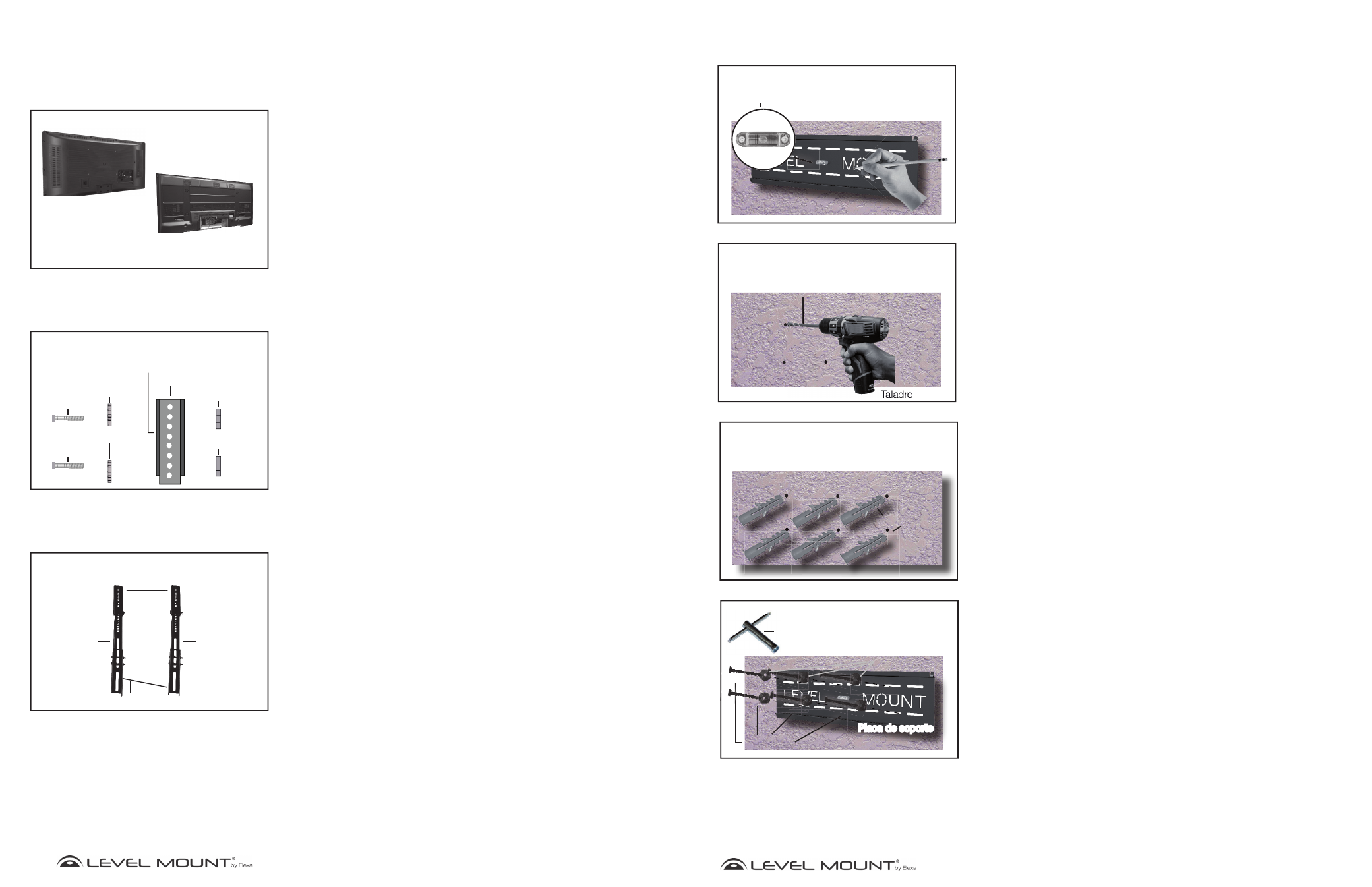
Imagen 13
Imagen 14
Imagen 15
Imagen 16
Pared de hormigón
Pared de hormigón
Nivel de burbuja
incorporado/
Nivel
Pared de hormigón
Pared de hormigón
Pared de hormigón
Pared de hormigón
Pared de hormigón
Pared de hormigón
Placa de soporte
Placa de soporte
Broca para
Broca para
madera 12 mm
madera 12 mm
Tacos para
Tacos para
hormigón
hormigón
Llave hexagonal
Tornillos
Tornillos
hexagonal
hexagonal
Arandelas
Arandelas
Placa de soporte
Montaje/Instalación
Opción B – Si las paredes son de hormigón
Para fijar la Placa de soporte al hormigón, colóquela a la altura deseada. Marque
los 6 agujeros con un lápiz cuando haya nivelado la Placa de Soporte usando el
Nivel de burbuja que viene incorporado o el nivel, tal y como muestra la Imagen
13.
Deje la Placa de soporte a un lado. Taladre 6 agujeros en el hormigón, en el lugar
marcado, tal y como muestran las Imágenes 14. Para taladrar los agujeros de los
tacos para hormigón (Bolsa 6) en el hormigón, utilice un taladro eléctrico con una
broca de 12 mm para madera.
Cuidado:
No utilice un martillo neumático, pues rompería y debilitaría el
hormigón.
Inserte los tacos para hormigón (Bolsa 6) en los agujeros, tal y como muestra la
Imagen 15, e introdúzcalos con un martillo hasta que queden a ras de la pared de
hormigón, como muestra la Imagen 15.
Para fijar la Placa de soporte a la pared de hormigón, utilice la llave hexagonal
para atornillar los 6 tornillos hexagonales con arandelas (Bolsa 6) en cada uno de
los tacos de hormigón, tal y como muestra la Imagen 16. Atornille bien, hasta que
quede fijo, pero con cuidado de no pasarse de rosca, pues de lo contrario podría
dañar el soporte o los tornillos.
Cuidado:
Debido al peso del televisor de pantalla plana, es fundamental
que utilice los 6 tornillos para fijar la Placa a la pared.