Dnt16i front panel, Dnt16i rear panel, System recovery mode switch – Lectrosonics DNT16i User Manual
Page 6: Usb port, Firmware update mode switch, Rs-232 serial port, Ethernet port, Programmable input and output port, Status leds, Dante ports
DNT Digital Processor
LECTROSONICS, INC.
6
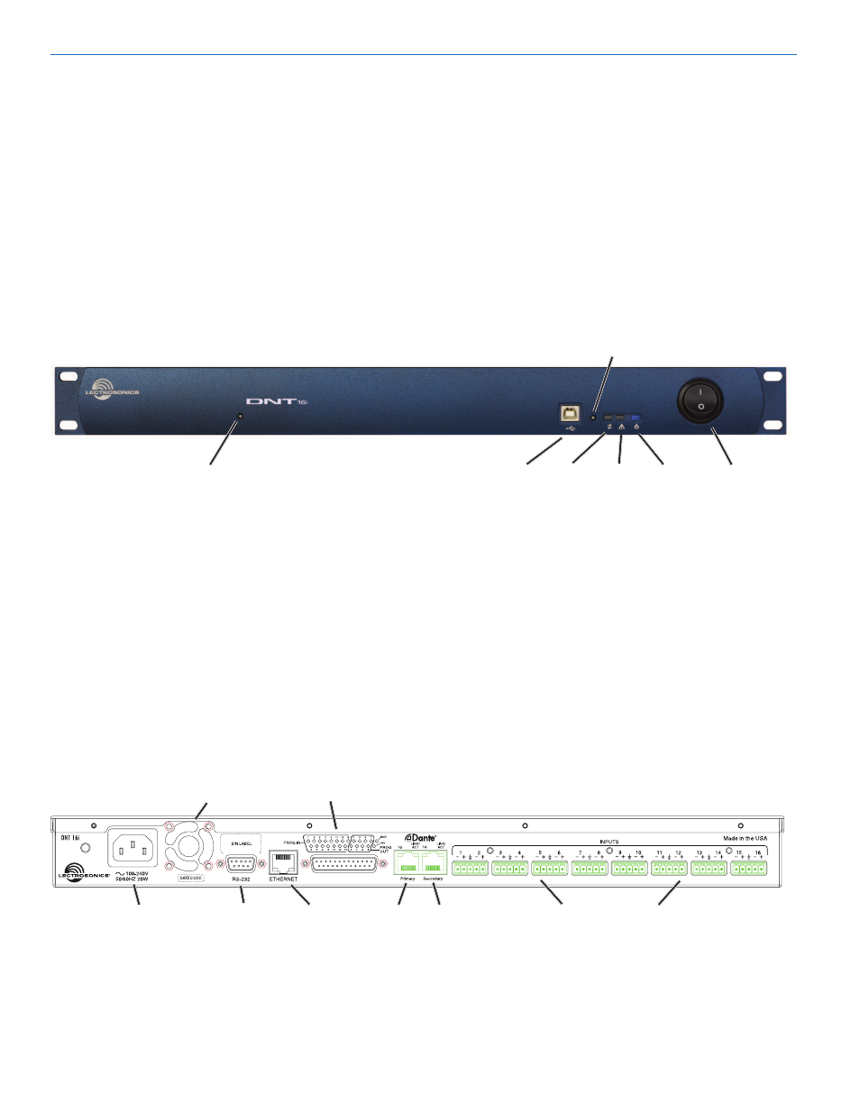
DNT16i Front Panel
System Recovery Mode Switch
Recessed switch is used to recover after a failed firm-
ware update.
USB Port
Standard USB connector for the setup and control
from a computer using a Windows or Mac operat-
ing system. The USB port is also used for firmware
updates.
Firmware Update Mode Switch
Recessed switch used to place the processor into the
firmware update mode.
DNT16i Rear Panel
RS-232 Serial Port
Used for control; typically with third party products
such as touch panel displays.
Ethernet Port
Used for control only. Does not pass audio.
Programmable Input and Output Port
Programmable inputs and outputs used to control
levels, settings, indicate the current state of a program-
mable input and control a variety of other parameters.
Status LEDs
• Comm LED - indicates USB, RS-232 and network
communication
• Alert LED - blinks to indicate fault or error
• Alert LED - glows steady in firmware update mode
• Power LED - glows to indicate power ON
Dante Ports
The network audio ports. Either port can be used with
a single network connection. When a second network
is configured for redundancy, all processors connected
to the network must have consistent connections, i.e.
all Primary ports connected to one network and all
Secondary ports connected to the other network.
Mic/Line Inputs
Analog inputs with adjustable gain from -10 to +60
dB in 1 dB increments; balanced differential floating
design (no pin 1 problem).
Power Inlet
RS232
Serial Port
Programmable Input
and Output Port
Analog Mic/Line Inputs 1 - 16
Cooling Fan
Outlet
Ethernet
Port
Primary Secondary
Dante Ports
POWER
Switch
USB Port
Alert
LED
Comm
LED
Power
LED
System Recovery
Mode Switch
Firmware Update
Mode Switch