Line level signals – Lectrosonics UM400 User Manual
Page 14
UM400
The best RF protection is accomplished by installing RF
bypass capacitors at the mic capsule. If this is not pos
sible, or if you are still having problems, capacitors can
be installed on the mic pins inside the TA5F connector
housing.
Install the capacitors as follows: Use 330 pF capacitors.
Capacitors are available from Lectrosonics. Please
specify the part number for the desired lead style.
Leaded capacitors:
P/N 15117
Leadless capacitors:
P/N SCC330P
All Lectrosonics lavaliere mics are already bypassed
and do not need any additional capacitors installed for
proper operation.
Caution: When wiring the connector, do not
use the connector body for any electrical
connections. A common mistake is to use
the connector body as an audio ground. The
connector body is already used as an RF
ground on VHF models and no other uses
permitted.
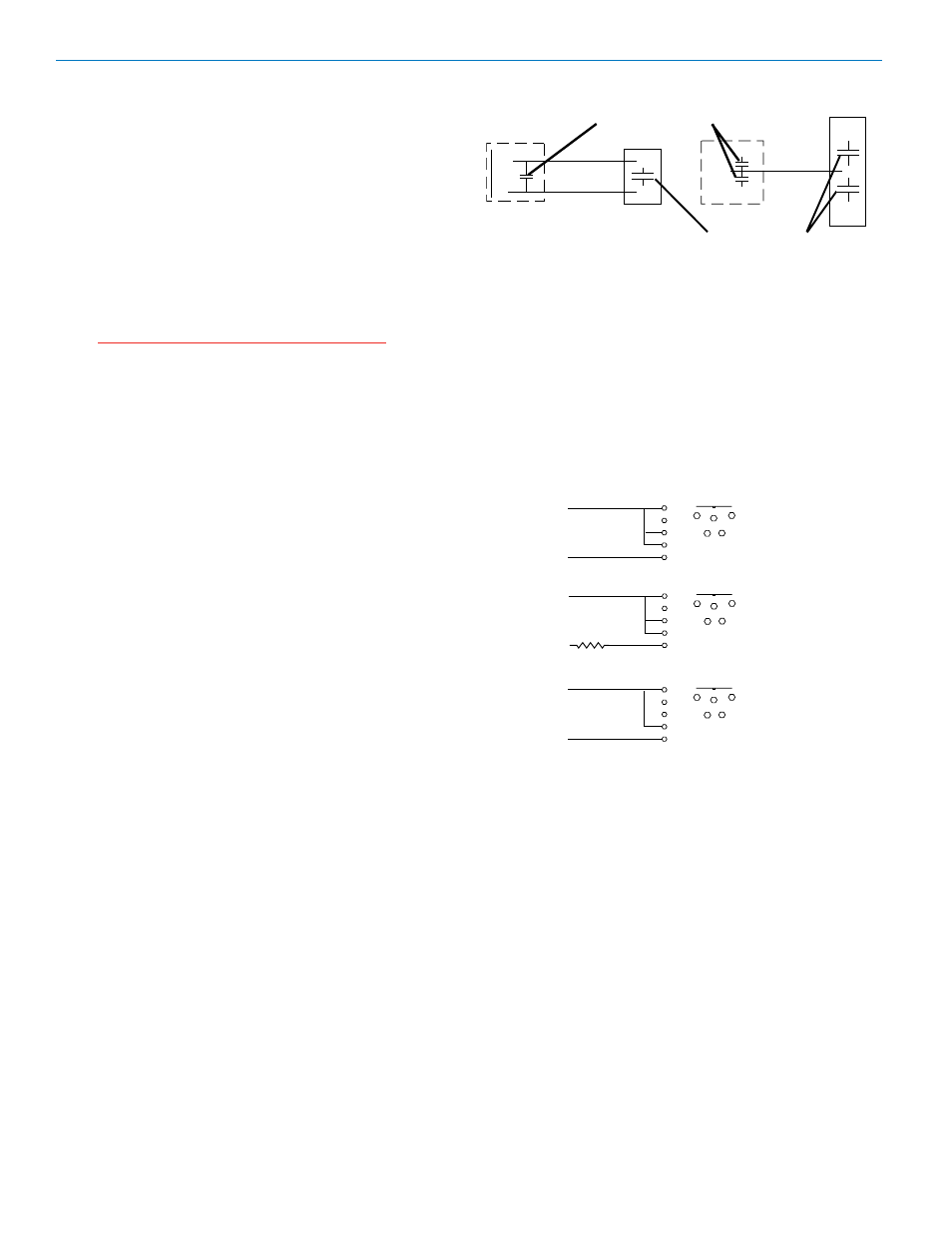
Line Level Signals
The normal hookup for line level signals is: Signal Hot
to pin 5, Signal Gnd to pin 1, pin 4 jumped to pin 1, and
pin 3 jumped to pin 1. This gives a 40dB attenuator that
allows signal levels much higher than 3V to be applied
without limiting.
If more headroom is needed, insert a 100k resistor in
series with pin 5. Put this resistor inside the TA5F con
nector to minimize noise pickup.
If lower than normal line levels (less than 1V) are
expected, use this hookup: Signal Hot to pin 5, Signal
Gnd to pin 1, and pin 4 jumpered to pin 1. This pro
vides a 20dB attenuator allowing signals as high as 3V
to be applied without limiting.
2 WIRE MIC
3 WIRE MIC
CAPSULE
CAPSULE
SHIELD
AUDIO
SHIELD
AUDIO
BIAS
TA5F
CONNECTOR
Preferred locations for bypass capacitors
TA5F
CONNECTOR
Alternate locations for bypass capacitors
PIN
Normal Hookup
5
PLUG
4
3
2
1
SHIELD (GND)
AUDIO
1
2
3
4
TA5F
5
PIN
More Headroom
5
PLUG
4
3
2
1
AUDIO
1
2
3
4
TA5F
5
100k
SHIELD (GND)
PIN
Lower Line Level
Hookup
5
PLUG
4
3
2
1
AUDIO
1
2
3
4
TA5F
5
SHIELD (GND)
1
LECTROSONICS, INC.